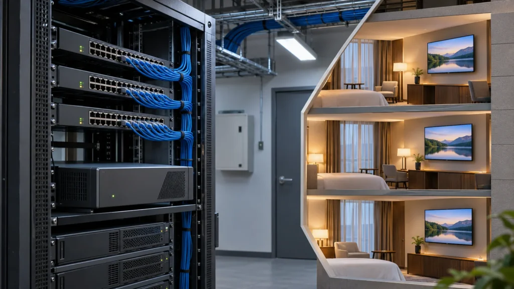
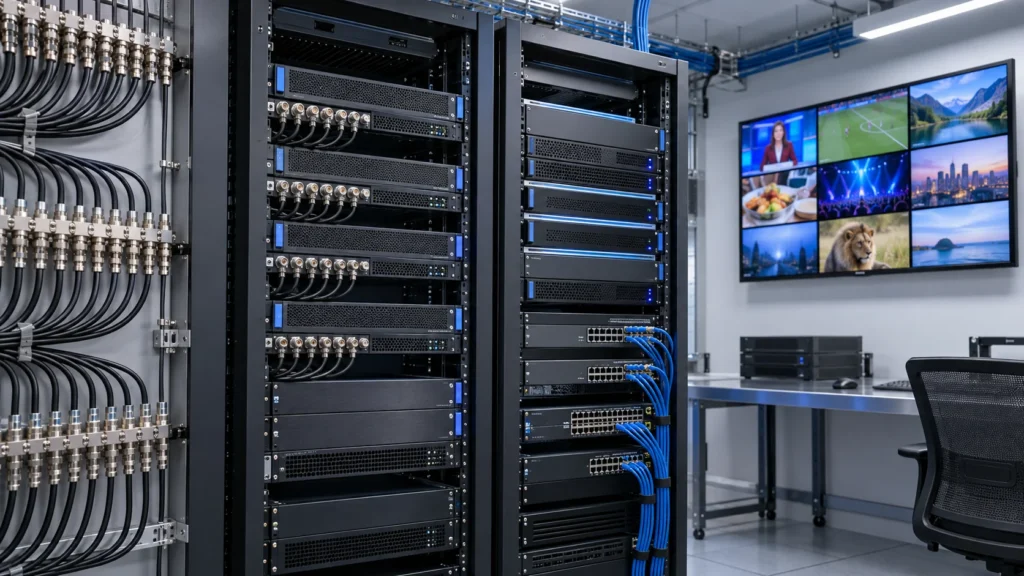
Define the distribution boundary before drawing the network
An IPTV distribution system carries television services from a headend or media server across a managed network to guest room televisions and set-top boxes. For a hotel project, start by documenting where the streams enter the network, which links carry them, which equipment decides where to forward them, and how a receiver recovers when one of those links fails.
This field guide is for hotel IT teams, AV integrators and contractors preparing a design or reviewing a tender. Use the commercial IPTV equipment range to identify the relevant equipment categories. The hotel IPTV streaming guide covers the broader service and receiver choices. Here the deliverable is a distribution plan that an installer can trace port by port and hand over to hotel IT.
Draw the path from the headend output to the core, then from the core to every floor switch and room port. Mark where Ethernet frames remain in one VLAN and where traffic crosses a routing boundary. Show the management network and any dependencies for address assignment, name resolution, time and service authorisation. A working TV menu may still coexist with a broken media path, so keep control and playback distinguishable in the drawing.
Confirm the physical handoff with the network contractor. List switch models, software versions, transceiver types, fiber routes, spare ports and cable test results. Record whether a path is shared with guest Wi-Fi, cameras, telephony or building controls. A logical VLAN isolates a forwarding domain, but services on the same uplink still compete for capacity. The hotel should know who owns both the switch configuration and the room-side wiring.
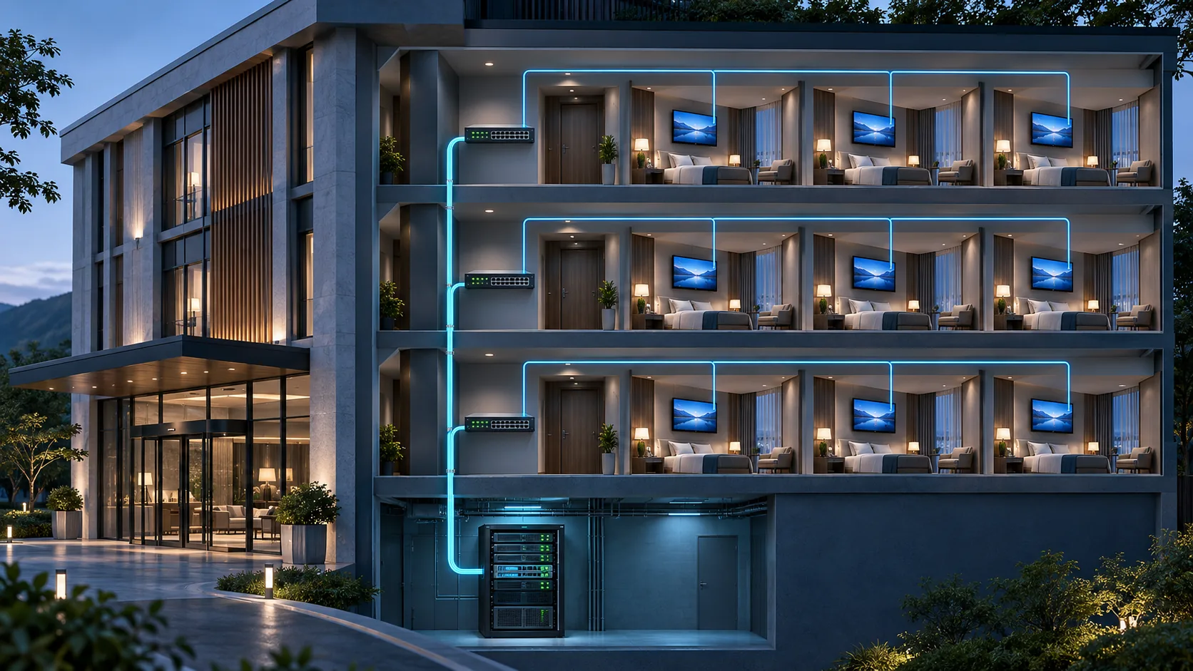
At the design review, pick one representative channel and one room. Trace the source, output address, core path, floor trunk, room port and receiver setting. Repeat for a room in each different wing or switch family. This simple walkthrough can expose an untagged port, a missing VLAN on an uplink or a service network that ends at the wrong floor.
Choose multicast, unicast or a hybrid by service
Use a service inventory to decide how each video workload should travel. A live channel lineup watched by many rooms on a managed wired LAN can be efficient in multicast. Receivers watching the same group can share a single copy on a given link, with switches or routers replicating traffic where branches diverge. Each interested branch still needs capacity for all distinct groups forwarded onto it.
Unicast delivery creates a session for an individual endpoint. It is useful for on-demand content, applications designed around HTTP playback, and receivers that cannot join the planned multicast service. Two rooms watching the same title may still consume two streams from the delivery node unless the chosen architecture adds caching or another distribution layer. Make the client count and point of replication explicit before quoting bandwidth.
| Service | Practical design option | Test at the receiver |
|---|---|---|
| Shared live lineup | Multicast on a managed wired TV network | Join, switch, leave and rejoin channels across each supported switch path |
| Personal or on-demand playback | Unicast from the server or application delivery node | Concurrent sessions, seek and resume, and behaviour at the intended bitrate |
| Mixed device estate | Multicast for compatible rooms and a validated unicast path for selected endpoints | Both delivery modes during the same busy period |
Check the entire receiver combination. A smart TV or box must understand the chosen transport, codec, audio tracks, subtitles and channel list. Firmware versions can matter even when TVs share a model family. Record the player, wired or wireless connection, and approved software version together in the acceptance matrix. A stream that works in a laptop player establishes a useful reference, but the hotel signs off the actual room equipment.
A hybrid layout also needs an ownership decision. Specify who operates the live gateway, where unicast sessions originate, and what happens when a room changes between live and on-demand. A centralized unicast service can become the busy-hour bottleneck even when floor links have spare capacity. Conversely, a healthy server does not prove that multicast membership works through every switch. Review both paths against the hotel IPTV procurement requirements before finalizing equipment.
If a hotel plans to deliver television over Wi-Fi in some rooms, validate those rooms as a separate service profile. Record access point models, the client connection, shared airtime, the delivery mechanism and how the player behaves when reception varies. An access point may treat multicast differently from the wired switches, and a change to unicast can shift the bottleneck back to the gateway. Run the wireless test while the guest network carries the agreed background load. Keep the wired pilot results separate so the commissioning team can identify which path needs work.
Set VLAN boundaries and assign multicast control
Start the IPTV VLAN design with a room port profile, a floor trunk profile and a record of which core interfaces own each VLAN. Identify which endpoints use an access port and which equipment actually needs tagged traffic. Keep management access limited to the intended network. Where a device needs DNS, time, licensing or another shared service, document the permitted flow and verify it with the site's security team.
Keep local membership and routed forwarding separate
IGMP allows IPv4 receivers to report interest in multicast groups. A switch that supports IGMP snooping can use those reports to constrain forwarding within a VLAN. The querier sends queries so that membership can be maintained. Record where queries originate for each receiver VLAN, whether the switch has learned the upstream multicast router port as intended, and how this behaves when the designated device restarts. RFC 9776 describes IGMPv3, and RFC 4541 describes snooping considerations.
If the headend and receivers are separated by a routed boundary, draw how multicast forwarding is established across it. An ordinary unicast route or a working ping does not show that the media groups can cross. Depending on the supported design, an integrator may use a multicast router, a validated proxy arrangement or an application gateway that changes the delivery mode. Check the actual device documentation and show the multicast path explicitly in the design.
For larger routed networks, a design using PIM Sparse Mode needs a routing and failure plan. For source-specific multicast, both the source and group identify the channel. Confirm that receivers, routers and snooping switches support the expected membership behavior before selecting that mode. When the receiver fleet has mixed firmware, test the least capable version rather than assuming all clients issue the same joins.
Give the channel list an owner. For each service record the source interface, group, UDP port, receiver profile and expected bitrate. Avoid duplicate assignments and use the site's approved address plan. If the network should prune traffic after viewers leave, test that behavior with two receivers on the same floor. Fast leave settings may require care on ports that serve multiple receivers. Validate with observed membership state and a packet capture instead of relying on a checkbox label.
Size the floor uplinks with a traffic worksheet
Calculate each link separately, in the direction that carries the streams. Write down distinct live groups on the link, their expected peaks, active unicast sessions, ordinary background traffic and a growth allowance. Make a second row for each failure case that can move traffic to the link. Confirm the agreed figures against counters during the pilot. In a system where traffic is always forwarded to a branch, use the full set of streams crossing it.
A worked example for one 30-room floor
Assume up to 18 different live multicast groups at 6 Mbit/s each on the floor uplink. That is 108 Mbit/s of live payload. If six independent on-demand sessions use 8 Mbit/s each, add 48 Mbit/s, for 156 Mbit/s of video payload. Adding a separate allowance of 70 Mbit/s for other services gives a working estimate of 226 Mbit/s before the project accounts for packet overhead and its operating reserve. These are illustrative inputs. Use measured peaks from the actual sources and player profiles when preparing a quote.
| Traffic on the example floor uplink | Input | Estimate |
|---|---|---|
| Live multicast payload | 18 distinct groups × 6 Mbit/s | 108 Mbit/s |
| On-demand payload | 6 concurrent sessions × 8 Mbit/s | 48 Mbit/s |
| Other services allowance | Measured or agreed planning allowance | 70 Mbit/s |
| Subtotal before overhead and reserve | 108 + 48 + 70 | 226 Mbit/s |
At the core, follow the actual topology. A headend link carrying every live group will have a different load from a floor link carrying a subset. Add unicast flows wherever they traverse shared links. Do not multiply every multicast stream by the hotel room count, and do not assume the floor estimate can simply be multiplied by the number of floors. The result depends on where paths branch and where streams are replicated.
Check the speed and constraints of each physical path. Look for a lower speed negotiated on an older cable, limited packet forwarding capacity, queue drops and forwarding-table limits. A link aggregation group may carry uneven traffic depending on how flows are assigned to members. Include the loss of one member or one switch in the worksheet if that condition is part of the uptime requirement. The IPTV server sizing guide covers the separate server-side load.
Once the pilot is running, measure utilisation, errors and drop counters at the headend, core and busiest access path at the same time. Capture the lineup and session mix used. If a test exceeds the normal target or a queue starts dropping, relate the counter increase to the exact traffic and interval. A busy-hour snapshot is easier to interpret when the headend, network and receiver logs use synchronized time.
Commission a pilot and isolate failures by boundary
Pick representative rooms before a full rollout. Include an endpoint on each switch family, one on a long cable run, one across a routed boundary if used, and both old and new TV or box firmware. Preserve a known working stream and a portable test receiver so that the team can compare the service at the headend, core and room. Use actual project channels and verify audio, subtitles and expected authorization where those features matter.
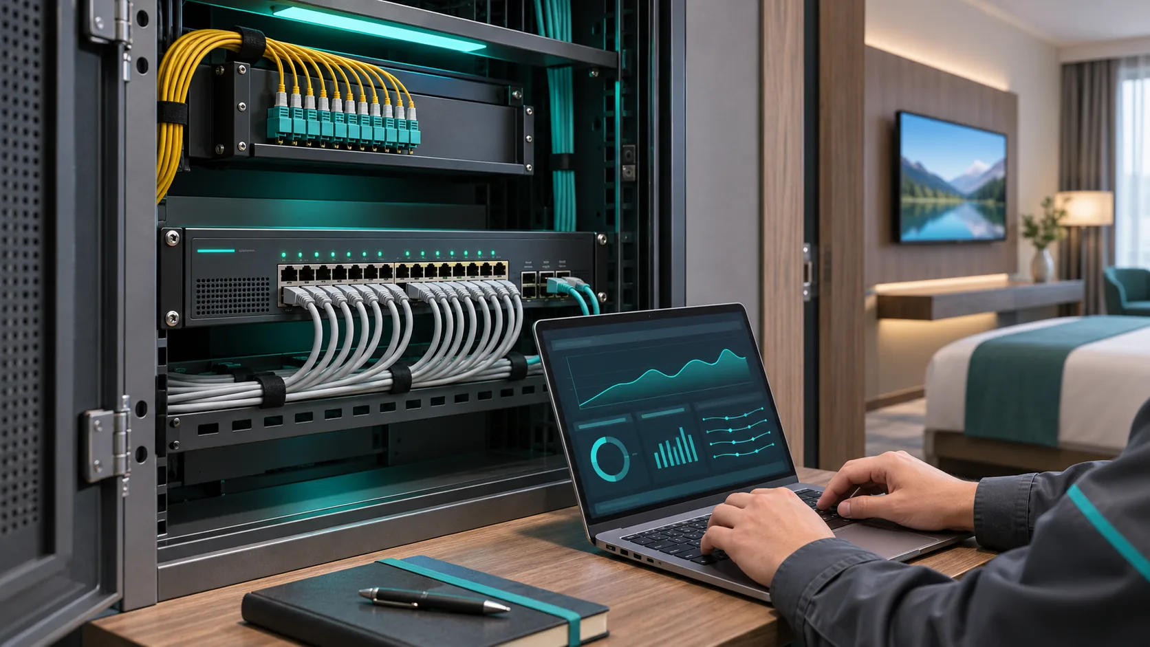
Run the pilot in a sequence that can be reproduced. First verify source and receiver at a known good location. Next join the same channel from a representative room, inspect group membership, and confirm packets reach that room port. Switch channels several times, let the original membership clear, and join again after a normal idle period. Then run the busy-hour mix from the traffic worksheet. Record where a symptom appears first and whether it is tied to the room, switch, channel or time.
| Observed symptom | Start the check here | Useful evidence |
|---|---|---|
| Channel works on the headend bench only | Core boundary and floor trunk | VLAN membership, group state and a capture on each side of the boundary |
| Picture drops after several minutes | Queries and membership aging | Time-aligned IGMP queries, reports and forwarding-table entries |
| One floor freezes during peak load | That floor uplink and access switch queues | Port utilisation, errors, discard counters and stream peaks |
| One TV model has sound but no picture | Receiver compatibility and stream encoding | Comparison on known good firmware with the same channel and output profile |
Agree a maintenance window before disconnecting anything. Under a controlled test, restart a floor switch, then check link recovery, address assignment, menu loading and live playback separately. For a redundant design, test the intended path failure while enough channels are active to demonstrate the load on the surviving path. Record the measured interruption and recovery times against limits agreed with the hotel.
Capture failures on both sides of the suspected boundary. A good output capture and missing room-port stream narrow the investigation to forwarding or access. A received stream with decoder errors points to a different investigation involving stream integrity or receiver support. Collect only the traffic needed for diagnosis and use the site's rules for storing captures. Save evidence with the room code, switch port and software version so the team can reproduce the fault later.
When testing a switch or gateway change, note the last successful packet, the first restored packet and the time at which the picture and audio return. An endpoint may need time to rebuild a session or reacquire the picture after forwarding resumes. If the network recovers promptly but a television remains blank, repeat the test with the same channel on a reference receiver before altering routing or increasing timers. Record both timings and the receiver version in the handover report.
Turn the network design into an acceptance package
Ask each supplier to return a topology with clear demarcation points. The headend scope should identify output formats and interfaces. The network scope should identify VLANs, access profiles, multicast boundaries, querier placement, route and failover responsibilities. The room scope should list approved receivers and firmware. The IPTV headend architecture guide helps separate equipment roles before comparing these scopes.
Request the design assumptions alongside the quote. State the room count and areas served, which sources can be redistributed, live groups per floor, concurrent unicast sessions, network paths, growth allowance and any equipment the hotel will reuse. Include any excluded work, from new fiber routes to replacement room receivers. A proposal with a supported switch model and a signed pilot method is easier to compare than one that only lists device quantities.
Give acceptance a named owner and a repeatable record. For each test, specify the room or port, channel, traffic condition, expected result, measured value and who signs it. Include normal joining, channel changes, an idle and rejoin check, peak traffic, reboot recovery and a representative fault. Use limits agreed for the property and endpoint fleet. Record any open exception, the temporary service path and the date for retest.
The handover should include the as-built topology, approved network and receiver profiles, a channel inventory, the uplink worksheet, pilot results and maintenance contacts. Store change-controlled configuration backups through the hotel's approved process. Ask for a short recovery guide that tells the operator which switches and uplinks to check when a room, floor or wing loses television. Preserve an approved rollback route for staged migration so teams can restore the previous service if a new floor does not pass acceptance.
For a renovation, sequence the floors and confirm which rooms remain on legacy service. Keep the pilot test set available after launch, especially when an access switch or TV firmware changes. Operational evidence should help the team distinguish a single-source outage from a forwarding failure or a receiver profile change. A usable design leaves behind enough detail for a different engineer to reproduce both normal behavior and the tests.
Related Products
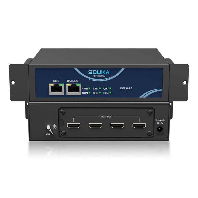
Related Solutions
IPTV Solution for Hotels
Deliver lag-free 4K live TV to every guest room, customize your interactive brand interface with zero coding, and automate database workflows. Our carrier-grade Linux streaming matrix bridges natively with global property management systems to eliminate integration friction and slash hardware deployment overhead.
Explore Solutions
IPTV Solution for Hotels
Deliver lag-free 4K live TV to every guest room, customize your interactive brand interface with zero coding, and automate database workflows. Our carrier-grade Linux streaming matrix bridges natively with global property management systems to eliminate integration friction and slash hardware deployment overhead.
Explore SolutionsFrequently Asked Questions
Yes. Our IPTV Streamers support multicast streaming for live TV distribution.
Multicast is especially suitable for large IPTV headend systems because one TV stream can be distributed to many IPTV terminals without creating a separate stream for every user.
This can significantly improve network efficiency.
Conclusion
Choose the delivery mode for each service, document where IPTV VLANs and multicast paths begin and end, and size every shared uplink for its own traffic and failure conditions. Confirm the assumptions in a pilot on the actual room devices. For a project review, share your floor plan, switch and receiver inventory, channel lineup, session estimate and acceptance targets. See the SOUKA hotel IPTV solution and request a distribution design review.