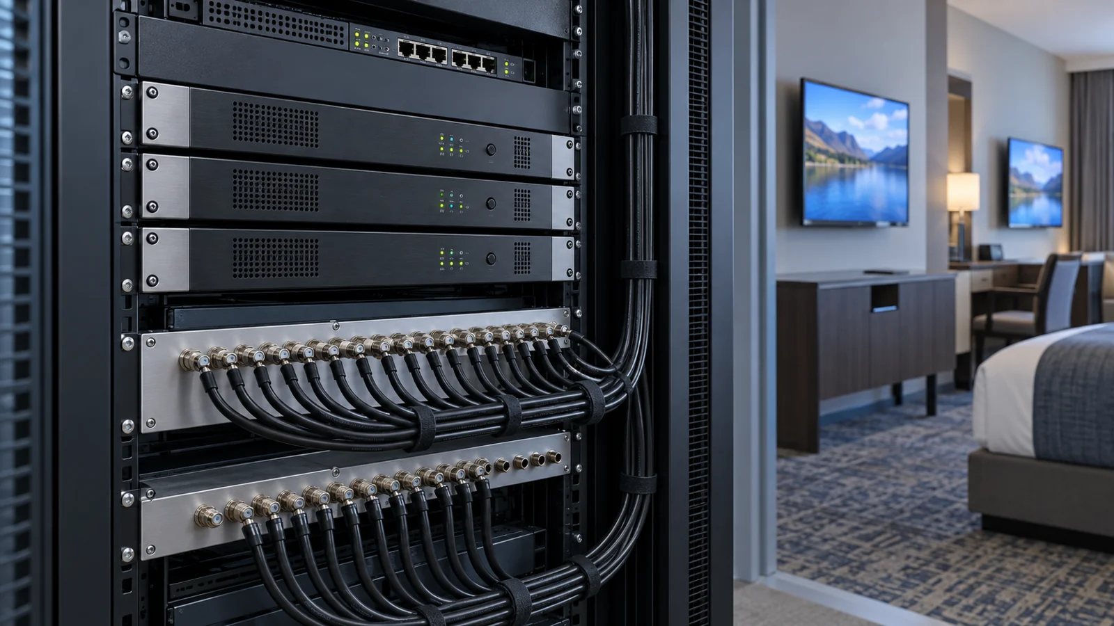
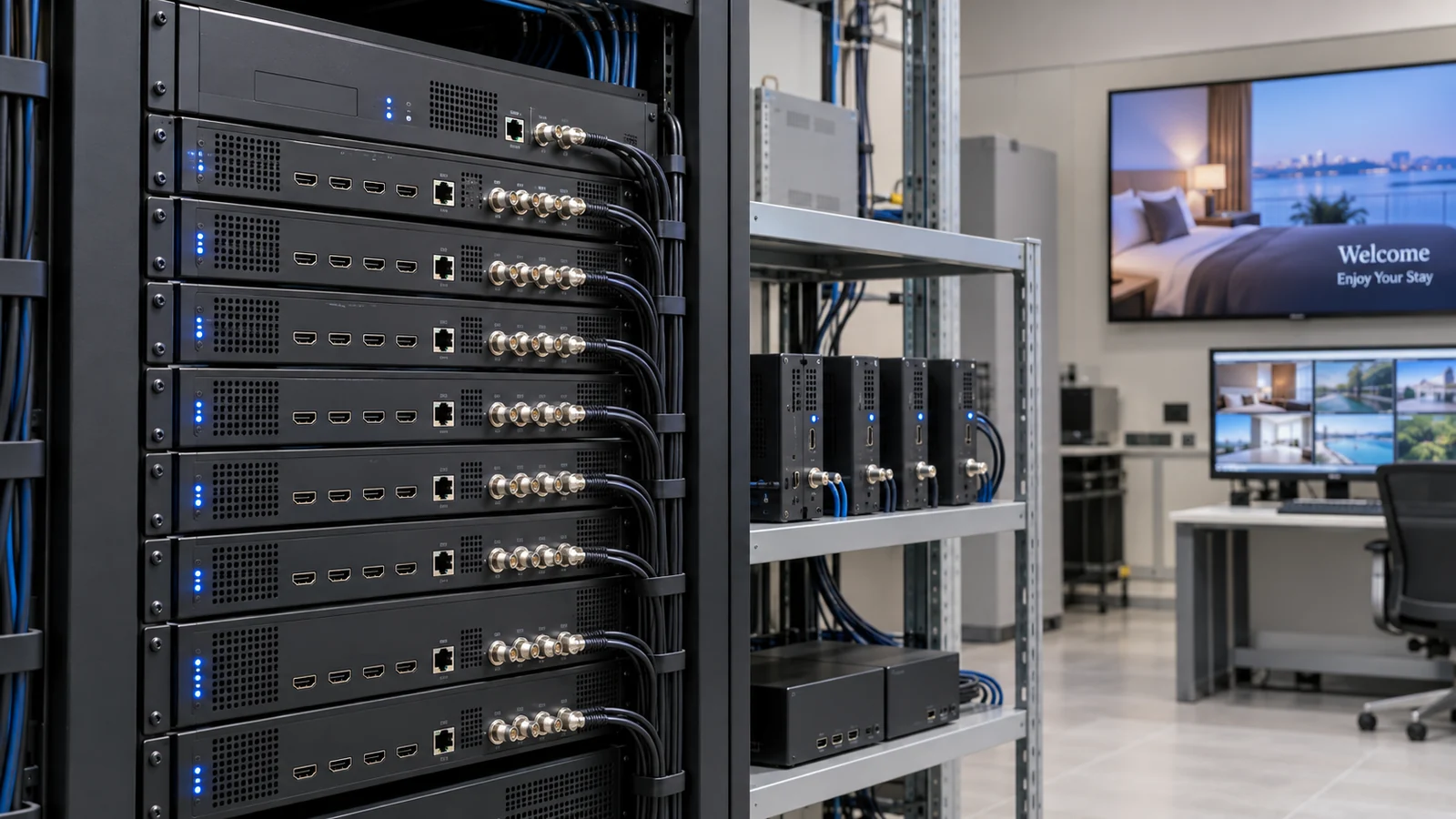
An ATSC modulator can distribute centrally selected television programs across a hotel's existing coax network, but a matching RF connector does not guarantee that every room television will decode the signal. The purchase decision depends on the tuner mode, encoded video and audio, channel information, and the performance of the installed distribution network.
This guide focuses on private, wired ATSC 1.0 hotel TV distribution. It helps hotel engineering teams, system integrators, and equipment buyers define a compatibility test, plan RF carriers, and issue a useful procurement specification before ordering a headend. ATSC 3.0 reception, cable QAM, and over-the-air broadcasting are different requirements and must not be treated as interchangeable.
Define the ATSC modulator requirement before selecting hardware
In a typical private television system, a source supplies video and audio to an encoder. The encoder creates compressed program streams, a multiplexer combines services where supported, and the modulator places the transport stream onto an RF carrier. The hotel's coax network delivers that carrier to compatible television tuners. The source may be an authorized receiver, a local information player, or another approved feed.
The important boundary is the signal delivered to the TV. An HDMI input specification describes what the encoder accepts. An ATSC output specification describes the RF and transport format. Neither statement alone proves that an installed television can display the complete service. Write the requirement as an end-to-end chain rather than buying from the number of HDMI sockets.
Give suppliers a concrete deployment description
State that the equipment is for a private coax network, identify the television models, and explain whether existing off-air or cable services will share the distribution plant. Record the current channel lineup and the guest-facing numbers that should remain unchanged. Where paid programming is involved, confirm the provider's commercial redistribution terms independently of equipment compatibility.
Start the equipment shortlist in SOUKA's digital TV modulator range, then request the exact output-standard option and firmware configuration. A catalogue covering several standards does not mean every purchased variant includes every mode. Document the agreed configuration in the quotation and acceptance checklist.
Separate ATSC 1.0, cable QAM, and ATSC 3.0
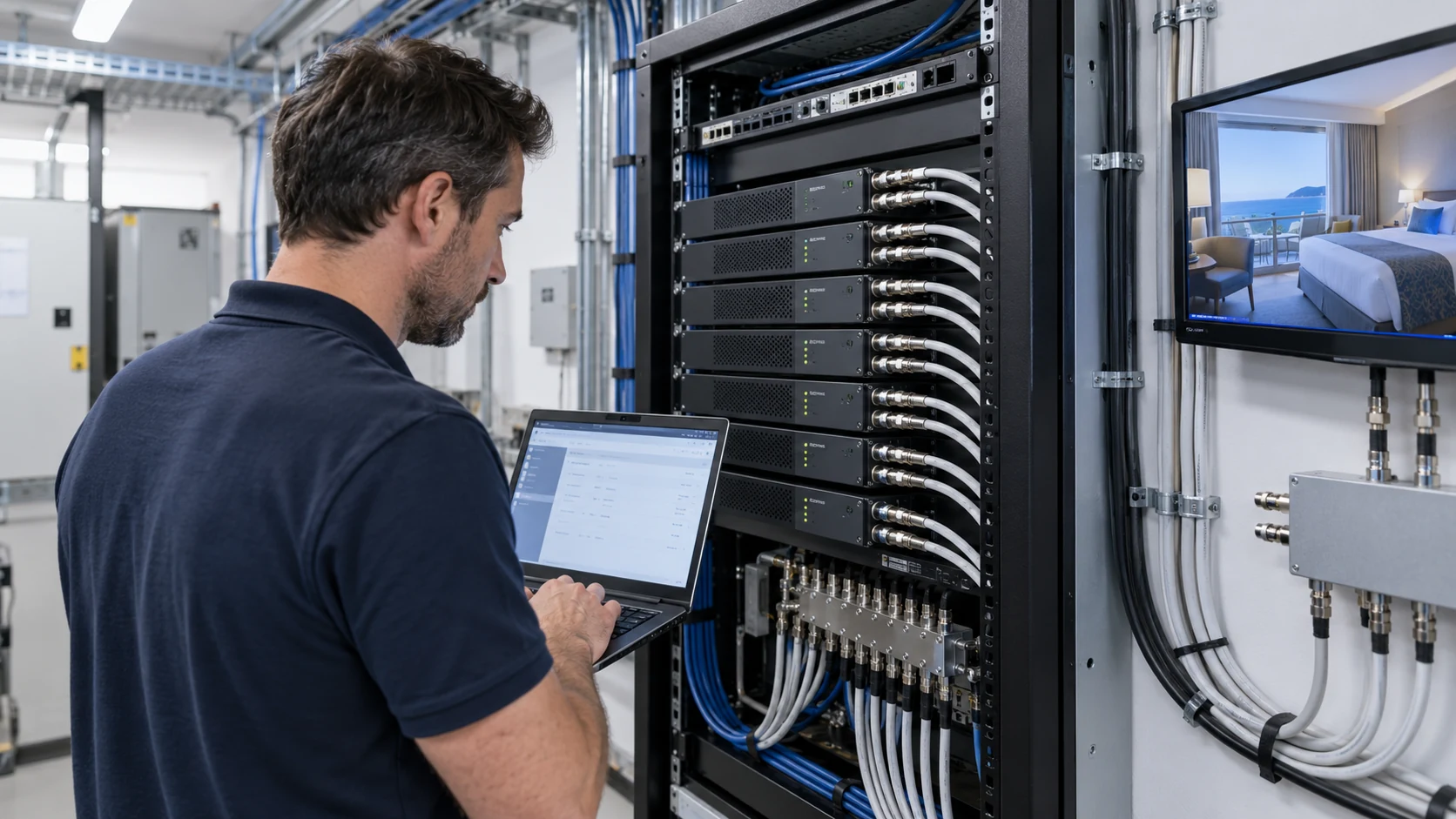
ATSC 1.0 terrestrial-style modulation uses 8VSB. Cable QAM uses a different modulation method even when a television offers both through the same antenna connector. The television's Air or Antenna scan and Cable scan may therefore produce different results. Confirm the actual reception mode on each installed model instead of assuming that the word digital covers both.
ATSC 3.0 is another system, not an extra feature automatically available in an ATSC 1.0 modulator. ATSC's A/300 system overview describes it as fundamentally different from predecessor systems. Specify the intended generation explicitly. Do not promise a NextGen TV upgrade through an ordinary firmware change unless the supplier documents the necessary hardware and system support.
| Requirement | What to confirm | Hotel procurement implication |
|---|---|---|
| ATSC 1.0 / 8VSB | Supported tuner mode, codecs, and channel information | Pilot the exact output with every TV family |
| Clear QAM / J.83B | Cable tuner support, scan behavior, and transport compatibility | Do not substitute QAM for 8VSB without testing |
| ATSC 3.0 | Generation-specific receiver and redistribution architecture | Treat as a separate technical specification |
| Multi-standard equipment | Purchased mode, licensing, firmware, and simultaneous-output limits | Record the supplied configuration, not just a family brochure |
A country-level broadcast standard is useful context but not a substitute for a room-TV inventory. Imported televisions, hospitality firmware, and replacement batches can create a mixed installed base. The deciding evidence is reliable reception on the actual equipment the property will keep.
Build a television compatibility matrix for the hotel
Create one row per television family, including model number, firmware version, room count, accessible tuner modes, supported codecs, and channel-cloning method. Add a representative physical TV to the pilot bench for each family. A new display in the supplier's office is not equivalent to the property's oldest hospitality model.
Test more than picture lock
Check video, audio, aspect ratio, captions where required, service name, displayed channel number, and behavior after power loss. Test remote-control tuning from the guest's normal interface. If the hotel locks installation menus, verify how staff will scan or clone channels without leaving guest access to configuration controls.
RF lock and successful decoding are separate results. A TV can detect the carrier yet show a black screen, silent audio, or an unsupported-format message. Video and audio settings must be accepted by both the encoder and the room television. A file format supported by a TV's USB player does not prove that its broadcast tuner accepts the same encoding.
For mixed-age installations, ask the supplier to propose conservative settings and demonstrate them. Keep a signed record of the settings that passed, then prevent deployment staff from changing them simply to improve a benchmark on one newer model. If a TV family fails, price the practical alternatives: another encoding profile, a compatible receiver, or a planned television replacement.
Use the broader hotel HD modulator buying guide when comparing the complete coax system. This article adds the ATSC-specific receiver and service-discovery checks that a general equipment comparison cannot settle.
Match video, audio, and source behavior to the receiver
A working HDMI monitor proves that the source can produce a picture locally. It does not prove that the encoder can capture that source continuously or that the television can decode the resulting RF service. Include the actual source receivers and players in the pilot, with their normal operating firmware and output settings.
Confirm accepted resolutions and frame rates separately from encoded output settings. Test startup, source standby, HDMI reconnection, resolution changes, and recovery after an encoder restart. For a hotel information channel, include the real presentation player rather than only a static test pattern. For motion-heavy programming, assess the intended quality profile on a representative screen.
Audio deserves its own acceptance line
ATSC's A/53 standards overview separates video, audio, multiplexing, and RF requirements. A modulator offering several audio options is not proof that every television accepts every option. Require the quoted audio mode to be tested, including volume consistency, lip synchronization, language selection where relevant, and recovery after a source change.
Content protection and distribution authorization also need a clear boundary. An encoder should not be purchased on an assumption that it can bypass protected HDMI content. Ask the source provider for an approved commercial output and redistribution arrangement. A technical input that works with an unprotected player is not evidence that a subscription receiver will work under all conditions.
The useful procurement result is an approved source-to-TV profile, with video and audio settings recorded together. Keep that profile with the configuration backup so that a replacement unit can restore the service rather than restarting the compatibility exercise.
Plan RF carriers and program capacity separately
The words channel and input are frequently used for different resources. An input is a source connection. A program is a service the guest selects. An RF carrier occupies spectrum and may carry one or several programs if the equipment supports multiplexing. Count all three separately when sizing an ATSC headend.
For standard ATSC 1.0 8VSB, A/53 Part 3 specifies a transport-stream rate of approximately 19.39 Mbps. That is the overall transport rate, not a video-only allowance and not a guaranteed number of HD services. Program video, audio, service information, and transport overhead share the available capacity.
Use a budget tied to actual content
List the target programs and their proposed encoding rates. Include audio and signaling allowances and any operating margin recommended for the chosen equipment. Where the encoder uses variable bit rates or statistical multiplexing, ask how simultaneous peaks are controlled. A demonstration with quiet scenes is inadequate evidence for a sports-heavy lineup.
An illustrative two-program multiplex is a planning exercise, not a product claim: two 7 Mbps video streams already consume 14 Mbps before audio and other transport requirements. The remaining capacity must be evaluated against the full configuration. More aggressive compression may add services but can reduce picture quality or exceed receiver compatibility.
Expansion needs spare source inputs, encoding capacity, multiplex capacity, available RF spectrum, and distribution headroom. Adding one service can require another carrier even when an input socket remains free. For the physical layout and failure implications, compare single-channel and multi-channel HDMI modulator architectures before deciding how much reserve to purchase.
Keep physical RF channels and virtual numbers consistent
The frequency carrying a service and the number displayed to the guest are not necessarily the same. ATSC service information can identify virtual channels with major and minor numbers. A television needs coherent signaling to discover the intended services and show useful names. Stable channel identities matter when hundreds of room TVs are configured from a shared master list.
ATSC's A/65 PSIP documentation is the reference for program and system information. For purchasing, translate this into observable requirements: correct service discovery, approved display numbers and names, no duplicate identities, and predictable scans on every TV family. Ask which fields the selected firmware exposes and what must remain fixed.
Test changes before applying them property-wide
Create a channel map containing the source, program identifier, RF frequency, virtual number, service name, and affected distribution branch. Have one person own the master version. An improvised change by a replacement technician can create duplicate channels or leave a room's cloned configuration out of step with the headend.
During a staged upgrade, test a spare or maintenance branch before replacing live carriers. Confirm the behavior of televisions that retain old channel lists, not just those freshly reset. If a rescan is necessary, include its labor and occupied-room implications in the project schedule. A stable signal is not a successful handover when guests can no longer find familiar channels.
Also test power-cycle behavior. The service list, hotel-mode restrictions, and preferred startup channel should survive normal operational events. Record the procedure for restoring the master channel list rather than relying on one technician's memory.
Survey the coax network and establish a measured RF plan
Before choosing an output level, inventory combiners, amplifiers, splitters, taps, wall outlets, and cable routes. Note frequency ranges, unused ports, aging connectors, and previous repairs. The RF signal must arrive inside the receiver's workable range at both the nearest outlet and the most difficult branch. A strong headend output alone cannot establish that condition.
Build a frequency plan showing existing services, proposed carriers, and reserved expansion space. Check whether all installed distribution components pass the intended frequencies. Avoid selecting a channel solely because the modulator menu permits it. The usable plant bandwidth, occupied spectrum, and ingress conditions can limit a practical deployment.
Measure quality as well as level
Use suitable test equipment for the selected modulation mode. Measure carrier level and appropriate quality or error indicators at the headend and representative room outlets. Record the measurement conditions and compare them with the supplier's limits and the receiver requirements. Do not invent a universal hotel threshold from one brochure's maximum performance figure.
Increasing amplification can make overload, distortion, or ingress problems worse. Test the complete lineup with all carriers active rather than tuning one service in isolation. A network that works with a small pilot may behave differently after adding many outputs. Include the nearest room, a long cable run, high-loss branches, and a known troublesome outlet.
Where the plant needs repairs, separate that work from the equipment quotation. The supplier should know the measured distribution conditions, while the integrator owns the installation survey and corrective work. This division makes acceptance failures easier to diagnose and prevents an otherwise suitable modulator from being blamed for a damaged connector.
Run an end-to-end pilot with a written acceptance checklist
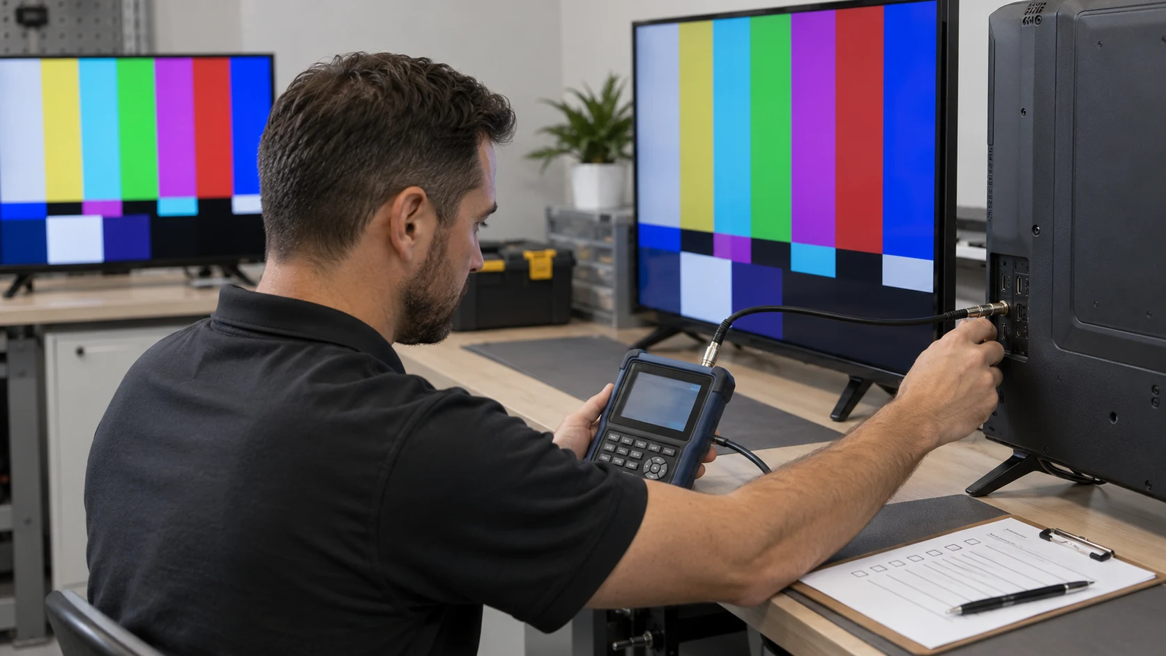
A useful pilot reproduces the source, encoding configuration, RF mode, representative coax components, and television families. Keep the original source settings and firmware versions in the test record. If the supplier changes any of them to resolve a failure, repeat the affected tests and update the approved configuration before production deployment.
- Confirm each source is captured and recovers after standby or reconnection.
- Scan every television family in the intended tuner mode.
- Verify picture, audio, captions when required, and displayed channel names.
- Activate the planned program lineup and assess motion-heavy content.
- Measure representative outlets with all RF carriers operating.
- Power-cycle sources, modulators, and TVs, then check service recovery.
- Restore a configuration backup onto the agreed replacement equipment.
- Record exceptions, corrective actions, and the final sign-off owner.
Agree the test duration, service continuity expectations, and acceptable recovery behavior with the hotel before testing. Do not label a short successful demonstration a completed long-term reliability trial. Where the property operates continuously, include an appropriate monitored soak test in the project plan.
Make failure descriptions precise. Carrier missing, carrier detected without decoded video, silent audio, wrong virtual number, and failures restricted to one branch point to different diagnostic paths. Record what was measured and which equipment reproduced the symptom. This is more useful than a generic instruction to increase the signal.
The handover package should contain the channel map, approved profiles, measurement log, backup files, hardware option list, and the restoration procedure. These records protect service continuity when hotel staff or the original installation contractor changes.
Compare ATSC-capable product options without assuming compatibility
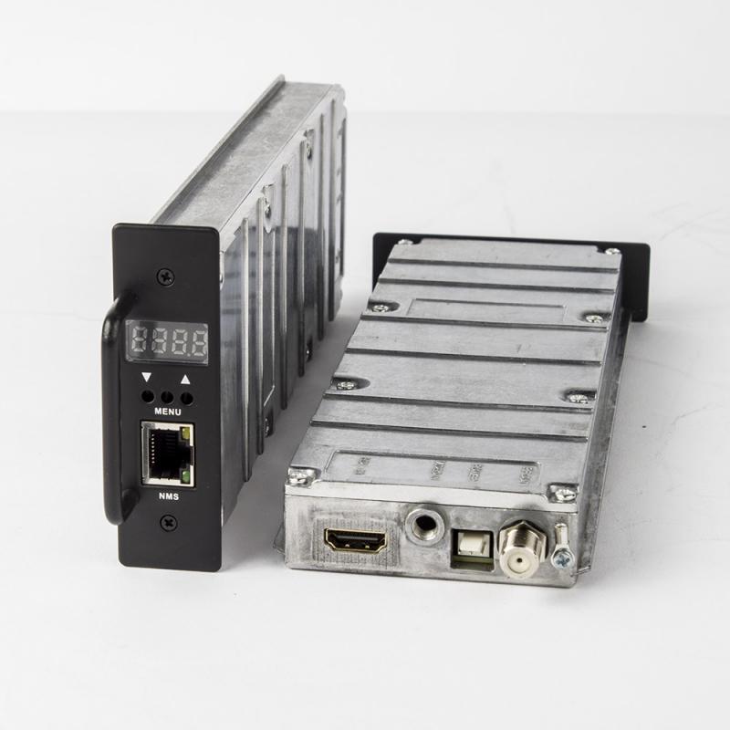
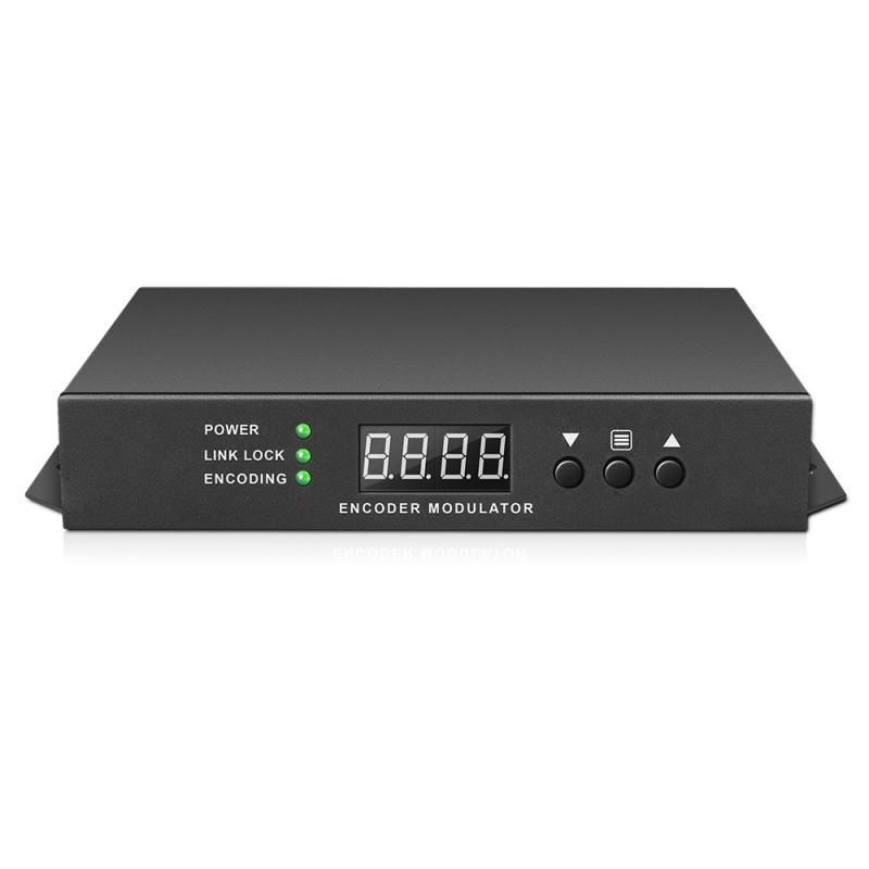
SOUKA offers multiple digital-modulator formats, but the best shortlist depends on sources, receiver support, and required capacity. Consider the single HD to RF ATSC/QAM modulator for a focused source requirement, and the encoder modulator with HD and RF loop where the documented loop arrangement matches the installation. Confirm each supplied standard option and encoding profile.
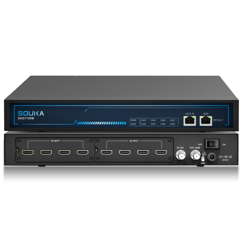
For a larger lineup, review the 4 or 8 in 1 HD encoder modulator. Its broader input and output configuration requires a program-to-carrier plan and a pilot of the selected output mode. Channel count or a multi-standard feature list must not be used as a substitute for room-TV compatibility.
Ask the same questions of every supplier
- Which exact hardware variant and firmware are included?
- Which video and audio profiles passed with the hotel's TV samples?
- How many programs and carriers are supported in the agreed configuration?
- What channel information can staff configure and back up?
- What happens after source loss, a power interruption, or a unit failure?
- How will technical support reproduce a fault using the saved settings?
Compare quotations on that shared specification. A lower equipment price may exclude the encoding mode, expansion option, support arrangement, or commissioning work that another supplier included. Ask for scope differences in writing. Avoid unverified guarantees such as works with all televisions, zero failures, or an unrestricted number of rooms.
Prepare a procurement brief and choose the right upgrade path
Send suppliers the TV compatibility matrix, source inventory, program lineup, RF plan, measured plant conditions, and expansion target. Include the site operating hours and the permissible interruption window. Ask for a proposed bill of materials, explicit assumptions, and a pilot acceptance plan rather than only a unit price.
Separate the functions that belong to the modulator from those supplied by other systems. Simple coax distribution provides centrally selected linear services. Personalized guest interfaces, on-demand experiences, or integrations with property-management systems usually require a wider platform. Evaluate SOUKA's hotel cable TV solution for a coax-led project and the hotel IPTV solution when the required guest experience extends beyond RF channel delivery.
Plan a maintainable transition
A hybrid upgrade may preserve useful coax service while introducing new network-based functions. That decision needs an assessment of the existing plant, television capabilities, room access, and operational priorities. It is not settled by calling one delivery method universally better. Keep the technical acceptance criteria separate for each distribution path.
Specify training, backup ownership, replacement availability, and support responsibilities before acceptance. A maintenance team should be able to identify a failing source, restore known settings, and explain the channel map without calling the original installer for every incident. Include spare capacity and spare hardware only where they address a documented growth or recovery requirement.
Use the resulting brief to request a project-specific review. The goal is a verified service chain and a clear commissioning scope, with commercial options compared on the same assumptions. That provides a stronger basis for purchasing than an attractive headline about resolution or channel quantity.
Related Products
Related Solutions
Cable TV Solution for Hotels
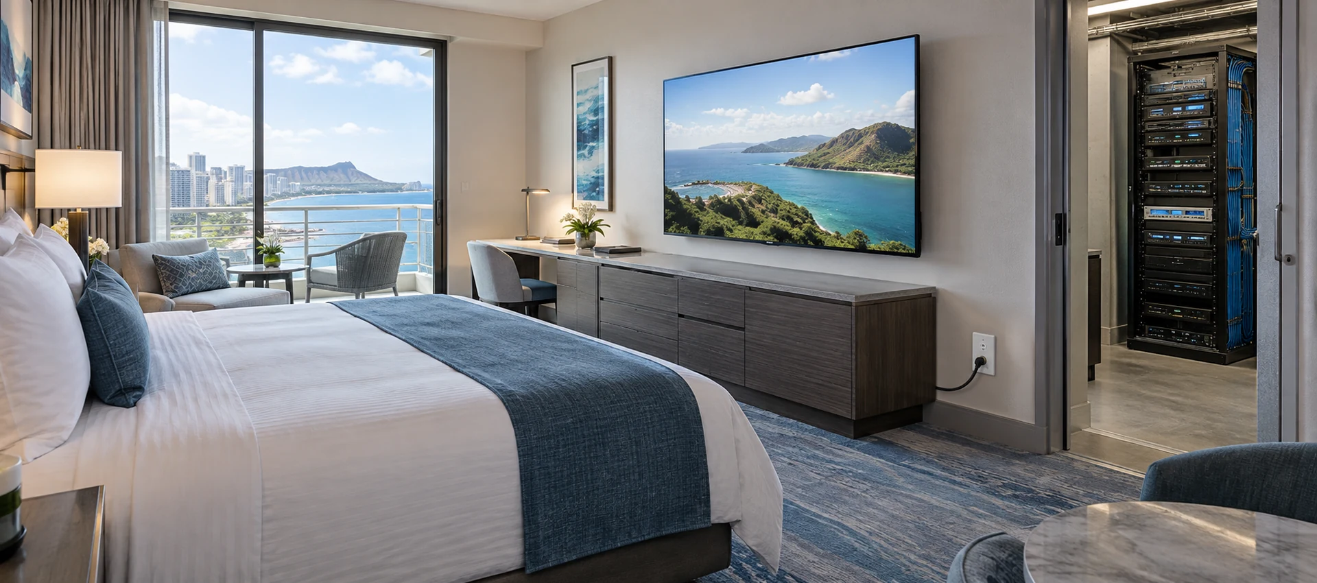
Deliver stable live television to every guest room without rebuilding the property network. SOUKA combines multi-source reception, high-density digital or analog modulation, RF combining, amplification, and centralized headend management for new hotels, phased renovations, and legacy coax upgrades.
Explore Solutions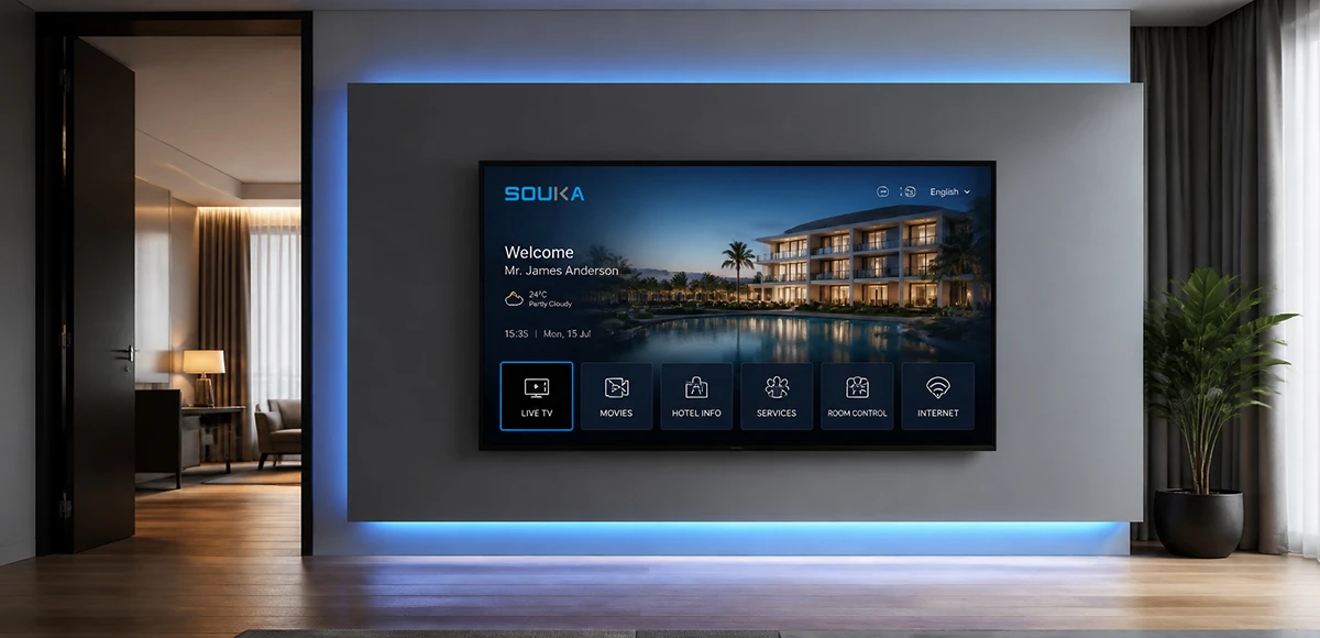
IPTV Solution for Hotels
Deliver lag-free 4K live TV to every guest room, customize your interactive brand interface with zero coding, and automate database workflows. Our carrier-grade Linux streaming matrix bridges natively with global property management systems to eliminate integration friction and slash hardware deployment overhead.
Explore Solutions
Cable TV Solution for Hotels
Deliver stable live television to every guest room without rebuilding the property network. SOUKA combines multi-source reception, high-density digital or analog modulation, RF combining, amplification, and centralized headend management for new hotels, phased renovations, and legacy coax upgrades.
Explore Solutions
IPTV Solution for Hotels
Deliver lag-free 4K live TV to every guest room, customize your interactive brand interface with zero coding, and automate database workflows. Our carrier-grade Linux streaming matrix bridges natively with global property management systems to eliminate integration friction and slash hardware deployment overhead.
Explore SolutionsFrequently Asked Questions
Conclusion
The right ATSC modulator for hotel TV is the one that passes an end-to-end test with the property's sources, televisions, and coax network. Specify ATSC 1.0 or another required output mode clearly, verify video and audio decoding, budget programs and RF carriers separately, and preserve consistent channel information. Keep ATSC 3.0 and cable QAM requirements distinct rather than assuming a shared connector makes them equivalent.
Build the purchase around measured conditions and a written pilot. Then keep the approved profiles, channel map, and restoration procedure with the hotel maintenance team. To discuss a SOUKA configuration, send your TV model list, source lineup, and RF distribution requirements. A project review can identify the relevant equipment options and the tests still needed before committing to a property-wide rollout.