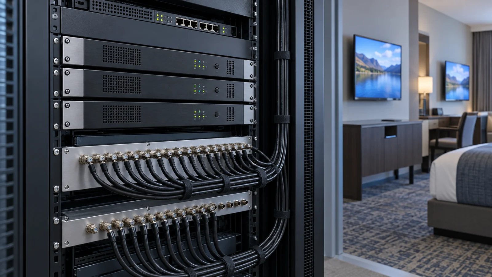
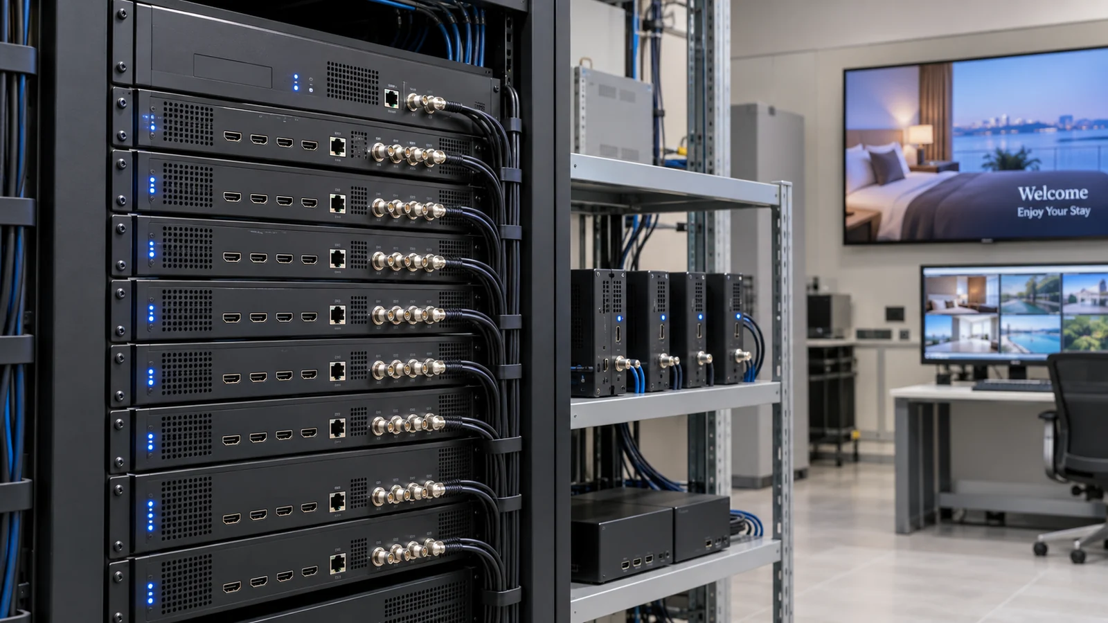
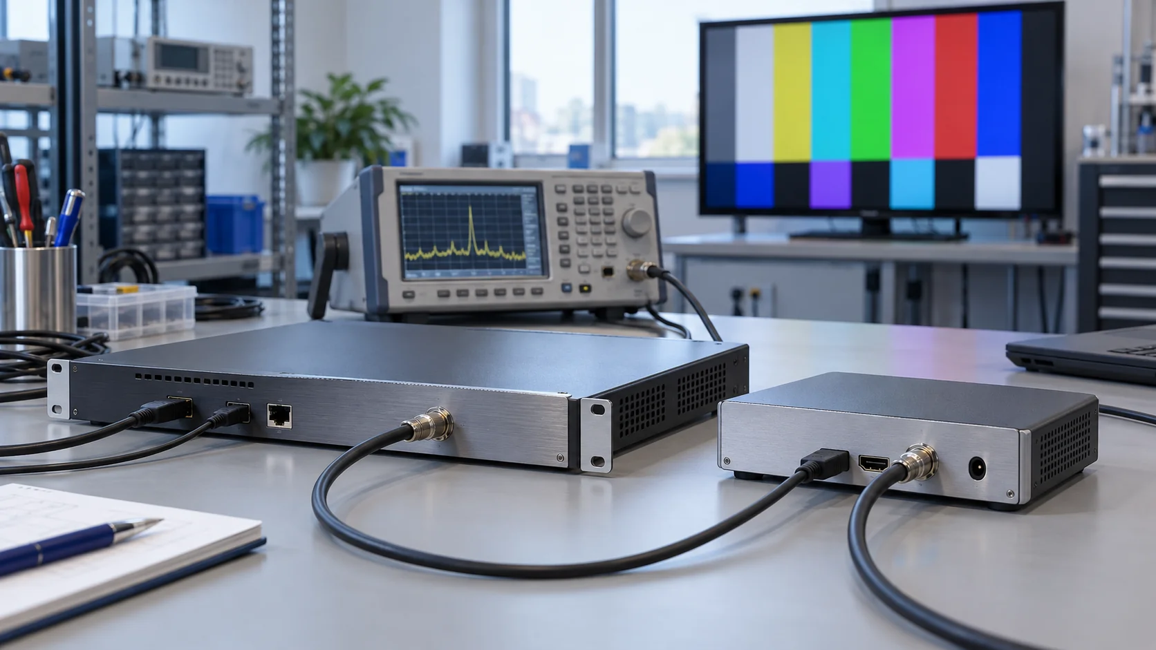
A high definition RF modulator prepares a video programme for reception through a television's RF tuner. In a typical HDMI encoder-modulator, the equipment accepts audio and video, compresses them into a transport stream, and produces a digital television RF signal for a coaxial network. The televisions must support the transmitted standard and the encoded programme.
For hotel owners, engineering teams and system integrators, understanding that chain makes specifications and fault reports much clearer. This guide follows the signal from the source to the guest-room television, then provides a practical method for isolating failures. Explore the SOUKA cable TV modulator range for project configurations; use the explanations below to identify what each stage must deliver.
What a high definition RF modulator actually does
“High definition” describes the video capability being claimed. It does not identify the RF transmission standard, the supported audio codec, the number of simultaneous programmes or the quality delivered at every outlet. A complete specification connects these details to the source devices and televisions in the building.
A simple passive cable adapter cannot perform this conversion. HDMI carries a different type of signal from a television antenna input. A working HDMI-to-RF modulator needs powered electronic processing. Equipment sold as an HDMI-over-coax extender is another category: it may require its own receiver at the far end and may not generate a TV channel that a standard television tuner can scan.
Encoder-modulator versus remodulator
An HDMI encoder-modulator begins with audio and video that need encoding. An IP-to-RF device may start with already encoded transport streams, process or remultiplex them, and create RF outputs. A tuner-to-RF unit may receive an existing broadcast service and remodulate selected programmes. These functions can coexist in a modular headend, but their input requirements differ.
Ask which stages are included in the quoted model and configuration. An RF output label alone does not prove the unit accepts HDMI, and an Ethernet port might serve only management. For a broader purchasing checklist, use the HD modulator buying guide for hotels. Here, the focus is how the stages interact during operation.
Digital RF distribution also differs from converting a source into an analog PAL or NTSC channel. An HDMI input on an analog unit does not establish HD delivery to the receiving television. Check the output system and received picture format explicitly before describing a retrofit as high definition.
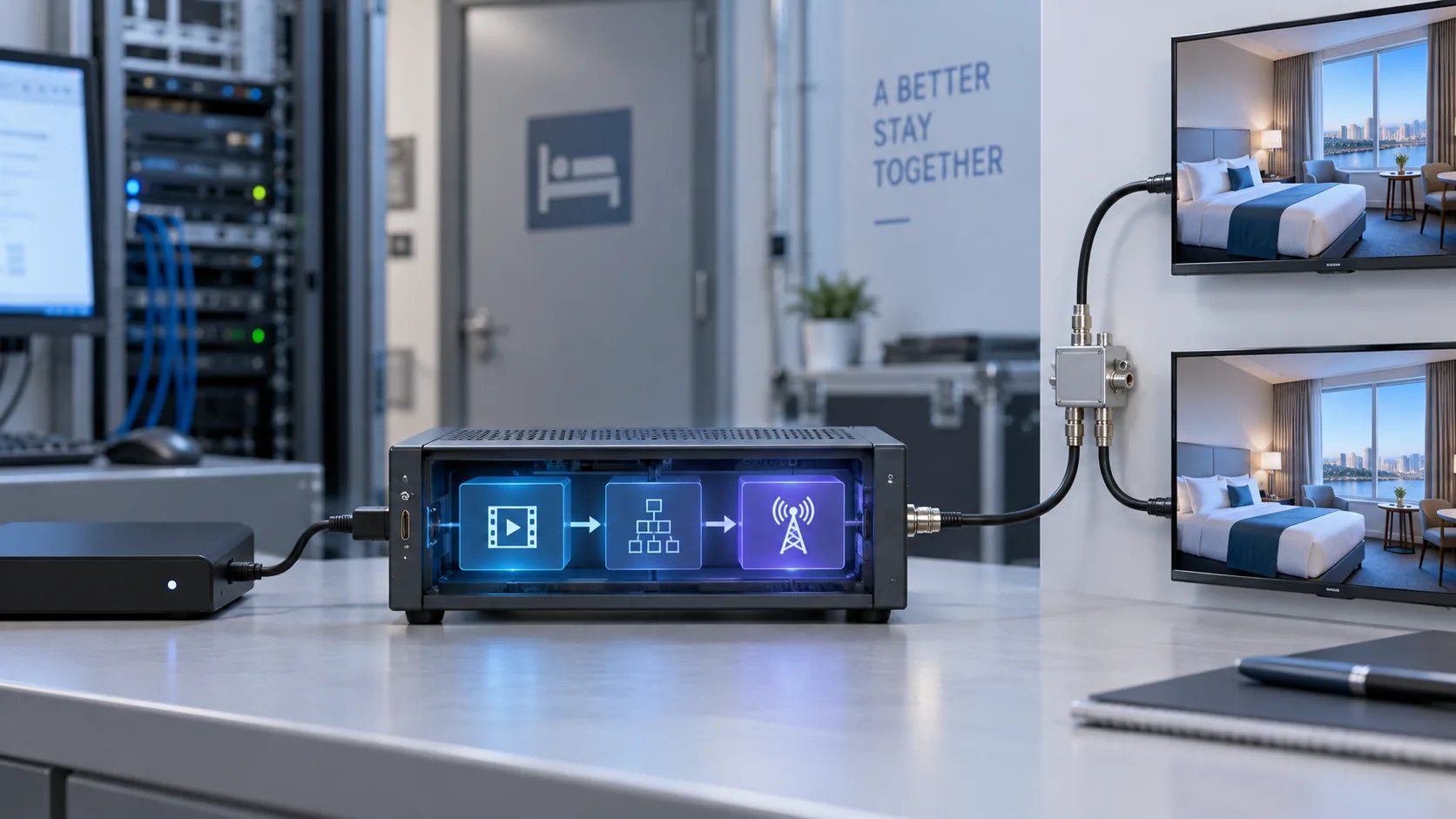
Stage 1: establish a stable HDMI source
Start at the source because every downstream stage depends on a usable input. Confirm the device's actual output timing, frame rate and audio format. A laptop, signage player and set-top box can all provide HDMI while behaving differently after startup, display detection or a software update.
Connect the source to a known compatible display to establish a picture-and-sound baseline. Then connect it to the intended modulator using an appropriate cable and the agreed output settings. Record the source model and settings rather than relying on an “Auto” mode that can change after equipment is replaced.
Separate input problems from distribution problems
A missing input lock or an unsupported timing should be resolved before adjusting coax amplifiers. Check the modulator's input-status page, where available, and compare it with the source baseline. HDMI loop-through can help observation, but a working loop-through picture does not independently prove that the encoder is producing a valid service.
Content protection is a separate compatibility and authorization issue. Check the source's protection requirements and the manufacturer's documented behaviour. Do not assume that a professional modulator bypasses HDCP, or that permission to view a programme includes permission to redistribute it throughout a property.
For continuous hotel use, include source restarts in the operational test. Observe whether the chosen output timing returns, whether audio resumes, and whether staff must acknowledge a menu. A source that works only after manual intervention may become a maintenance burden even when its picture quality is acceptable.
Record one known-good source configuration before introducing additional inputs. That reference lets an engineer substitute a controlled signal later and distinguish an upstream source change from a fault in encoding, modulation or the building network.
Stage 2: encode video and audio for the receiving televisions
The encoder converts the incoming audio and video into compressed elementary streams. The selected codec, profile, level, resolution, frame rate and audio format must all fit the receiving televisions. RF tuner compatibility and video-decoder compatibility are different checks: a television can find a service yet fail to display its programme.
For example, a receiving set may support a particular RF system without supporting every codec that a newer encoder offers. H.264, H.265 and MPEG-2 cannot be treated as interchangeable options across an installed fleet. Verify the exact television models, market versions and firmware that will remain in service.
Bitrate is part of a service budget
Video bitrate influences both picture quality and the capacity needed downstream. Fine detail and rapid movement can place different demands on the encoder from a mostly static welcome screen. Compare representative source material under the intended configuration instead of treating one attractive demonstration as proof for every programme.
Audio needs its own test. A visible picture does not guarantee that the television supports the selected audio format or that synchronization is acceptable. Listen on representative receiving sets, check channel changes, and repeat after a source restart. Keep the agreed audio setting in the configuration record.
Latency accumulates across encoding, buffering, modulation and receiver processing. It matters when a programme is shown in adjacent spaces or compared with a direct local display. Measure the complete path under consistent conditions if timing is important; a single component's advertised delay is not the end-to-end result.
When an RF channel locks but picture or sound fails, this stage deserves attention before increasing output power. Confirm the encoded service is valid and compare it on another known compatible receiver. Keep the source and RF settings fixed while changing one encoding variable at a time.
Stage 3: multiplex programmes and create an RF channel
Multiplexing arranges encoded services and their signalling into a transport stream. Modulation then maps that stream onto an RF signal using the selected television system. Programme count, physical input count and RF carrier count describe different resources and should appear separately in a channel plan.
Several programmes can share one carrier when the headend supports that arrangement, their combined transport bitrate fits, and the receivers understand the result. The usable capacity depends on the standard and configured mode. Reserve room for audio, signalling and operating margin rather than adding only the nominal video bitrates.
Keep physical and displayed channels distinct
The RF frequency identifies a physical transmission channel. A programme name or displayed channel number identifies a service presented to the viewer. Changing the displayed number does not necessarily move the carrier, while moving the carrier can require a new scan or managed channel-list update.
The ATSC A/53 specification separates video, audio, transport and VSB transmission functions. The DVB coding and transport overview describes its terrestrial and cable systems. These references explain why “digital RF” is not one universal format. Specify the actual system supported by each receiver family.
Do not interpret a constellation value by itself as a complete system label. A parameter must be read in the context of the relevant modulation standard and mode. For projects considering ATSC, the ATSC modulator hotel compatibility guide covers receiver checks in greater detail.
Save frequency, bandwidth, output mode, service identifiers and programme names together. A later adjustment to only one field can make a service disappear from an existing channel list even though the modulator remains powered and an RF carrier is present.
Consider a planning example with four independent HDMI sources: a welcome player and three authorized programme feeds. That means four source signals to process, but it does not establish that four RF carriers are required. First identify which inputs the proposed chassis can encode simultaneously. Then determine how its services can be grouped into transport streams and which RF modes the installed televisions receive. Only after those checks can the engineer assign carriers and frequencies. This example illustrates the planning sequence; it is not a capacity specification for a particular SOUKA model.
Stage 4: deliver the signal through the hotel coax network
After modulation, the signal still needs to reach the television within the receiver's operating limits. Combiners, splitters, taps, connectors, cable runs and amplifiers affect that path. A high-quality headend output does not establish acceptable reception at every room.
A passive split reduces the power delivered to each branch. An amplifier can compensate for some distribution loss, but cannot repair an incompatible codec or recreate information already corrupted upstream. Excessive level can overload equipment, so raising output indiscriminately is not a reliable response to pixelation.
Measure at meaningful boundaries
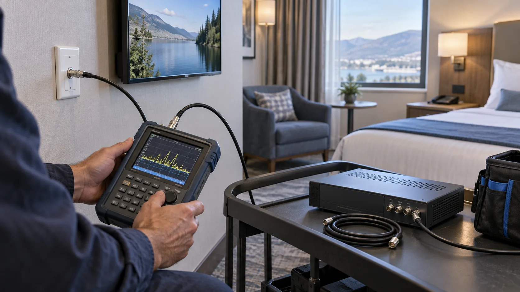
Record a baseline at the modulator output with a suitable instrument and safe measurement setup. Then compare the combined output, representative branch points and room outlets. Select the correct measurement mode for the transmitted system. Level, MER and BER provide different information; interpreting one without its test conditions can hide the actual problem.
Measure with the intended carriers active. Aggregate loading matters when channels share amplifiers or combining equipment, and a one-carrier test does not represent a fully populated headend. Document existing frequencies before introducing a new service so that an apparently empty channel does not disrupt another part of the property.
The number of televisions is primarily a distribution-design question. It is not the same as the number of HDMI inputs or programmes. A project with many rooms may distribute a small common channel package, while a smaller venue may require several independent sources and a more complex headend.
Use the Cable TV Solution for Hotels as the commercial starting point for a coax survey and configuration review. Provide the existing network drawing, receiver list and current channel plan so that equipment selection includes the actual distribution conditions.
Stage 5: tune, decode and operate the guest-room television
The television must locate the RF service, interpret its signalling and decode its audio and video. Confirm the correct tuning mode and country or region settings using the manufacturer's instructions for the installed model. A hospitality television may limit guest access to scanning or channel-list controls.
Test the full room inventory by representative model families, including older sets retained during a phased refurbishment. Marketing descriptions for a newer television series cannot establish compatibility for every earlier unit. Record which models were tested and which settings produced the accepted result.
One common programme is not an interactive service
A modulated channel normally distributes a programme to compatible receivers. It does not, by itself, create guest-specific menus, individual video-on-demand sessions, PMS integration or room-control functions. Those requirements involve additional applications, endpoints and system integration.
When the project needs personalized services, compare the RF architecture with an IPTV solution for hotels. Existing coax and compatible tuners can support a useful common-channel system; the best migration path depends on the services required and the infrastructure available, not on an assumption that one delivery method always replaces the other.
Check practical operation as well as initial reception. Verify channel names, ordering, picture, sound, switching and behaviour after the television loses power. Establish how channel-list updates will be deployed and who can change tuning settings during maintenance.
A successful sample-room test becomes a reference configuration. Preserve the television model, firmware, tuning mode and channel-list version with the headend settings. This makes later reports such as “one floor cannot find the welcome channel” much more useful to the engineering team.
Isolate failures by the last stage that still works
Use the signal chain to narrow the fault before changing settings. Establish a controlled short path from the known-good source through the modulator to a compatible television, with attenuation or other measurement provisions where required. Compare that baseline with the affected outlet. Avoid connecting a sensitive receiver or meter to an unsuitable signal level.
| Observed symptom | First boundary to check | Useful next evidence |
|---|---|---|
| Modulator reports no HDMI input | Source, timing and HDMI connection | Direct-display test and input-lock status |
| Carrier present, no service found | RF mode, tuning and service signalling | Correct-standard analysis and TV scan settings |
| Service found, picture absent | Encoded stream and decoder compatibility | Codec profile and known-compatible receiver test |
| Picture works, audio absent | Source audio and encoded audio format | Audio settings and another receiver family |
| Baseline works, distant rooms fail | Distribution branch and outlet conditions | Level and quality comparison along that branch |
| Failure appears after adding channels | Transport capacity and aggregate RF loading | Full-load bitrate, channel-plan and RF measurements |
These are investigation starting points, not automatic diagnoses. A missing service can have several causes, and an intermittent fault may cross stages. Note whether the failure affects one programme, one television family, one branch or the whole building; that scope is often more informative than a screenshot of a blank screen.
Change one variable, repeat the same observation, and save both results. If a change does not help, return to the recorded baseline before trying another. This prevents a temporary combination of unrelated adjustments from becoming an undocumented production configuration.
For a supplier comparison or formal acceptance test, use the professional HDMI modulator comparison and RF test checklist. Pairing that checklist with this stage-by-stage method connects the purchasing requirements to evidence that an engineer can collect on site.
Build a handover record that supports future expansion
A useful handover package preserves the decisions behind a working installation. Include the source inventory, receiving-TV inventory, signal-flow drawing, channel plan, approved settings and baseline measurements. Add equipment versions, backup locations and the responsible integrator or supplier contact.
Keep capacity and compatibility records together. An empty physical input does not prove there is spare encoding capacity under every operating combination, and spare transport bitrate does not prove an additional RF carrier fits the existing frequency plan. Check each affected stage when adding a programme.
Document restart and recovery
Record what happens after source loss, modulator restart and television power interruption. Note which services recover automatically and which require action. Define the escalation procedure before the property depends on the system, and keep a recoverable configuration backup under the owner's control.
For larger headends, the single-channel versus multi-channel architecture guide explains expansion and failure-domain tradeoffs. Use it alongside the operational record rather than treating chassis density as the only planning criterion.
SOUKA's product and solution pages provide starting points for discussing commercial configurations. Submit the actual source formats, required RF system, programme count and television models for model-specific confirmation. Avoid transferring a feature or measurement from one product page to another unit without written confirmation for the proposed configuration.
Finally, attach an agreed change process to the handover. Preserve the baseline before a firmware update or channel addition, identify the affected receivers, and schedule verification of representative outlets. A clear rollback point reduces disruption when a new source, encoding profile or service list behaves differently from the commissioned setup.
Related Products
Related Solutions
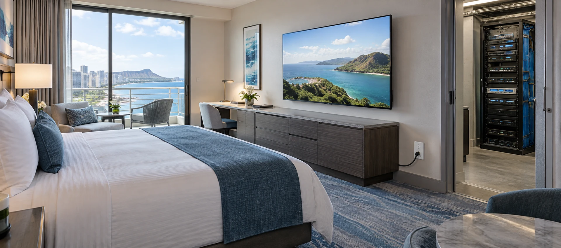
Cable TV Solution for Hotels
Deliver stable live television to every guest room without rebuilding the property network. SOUKA combines multi-source reception, high-density digital or analog modulation, RF combining, amplification, and centralized headend management for new hotels, phased renovations, and legacy coax upgrades.
Explore Solutions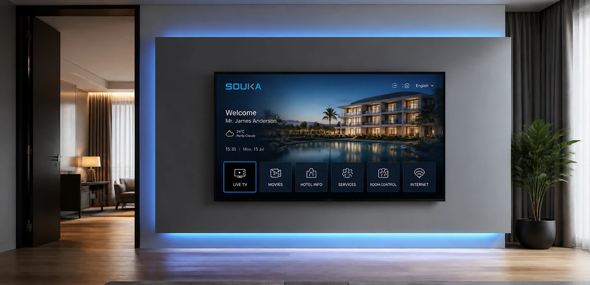
IPTV Solution for Hotels
Deliver lag-free 4K live TV to every guest room, customize your interactive brand interface with zero coding, and automate database workflows. Our carrier-grade Linux streaming matrix bridges natively with global property management systems to eliminate integration friction and slash hardware deployment overhead.
Explore Solutions
Cable TV Solution for Hotels
Deliver stable live television to every guest room without rebuilding the property network. SOUKA combines multi-source reception, high-density digital or analog modulation, RF combining, amplification, and centralized headend management for new hotels, phased renovations, and legacy coax upgrades.
Explore Solutions
IPTV Solution for Hotels
Deliver lag-free 4K live TV to every guest room, customize your interactive brand interface with zero coding, and automate database workflows. Our carrier-grade Linux streaming matrix bridges natively with global property management systems to eliminate integration friction and slash hardware deployment overhead.
Explore SolutionsFrequently Asked Questions
Conclusion: specify and test the complete signal path
A high definition RF modulator is one part of a complete source-to-screen system. The source must provide a supported input, the encoding must suit the television, the transport and RF configuration must match the receiver, and the coax network must deliver an acceptable signal at the outlet.
Use those boundaries to prepare a requirement sheet and investigate failures. Keep a known-good baseline, test representative room televisions, document the channel plan, and retain the configuration that passed commissioning. This gives procurement teams and service engineers the same practical reference.
Contact SOUKA to review your hotel RF modulator configuration with source details, television models, programme requirements and the existing coax layout. Request confirmation of the proposed model, operating combination and site-testing scope before placing the order.