To compare HDMI modulators for professional use, start with the televisions and distribution network that must receive the signal. An HDMI input and a high-definition label do not establish compatibility. The encoding format, RF standard, channel plan, signal quality and recovery behaviour all need to match the installation.
This guide gives hotel engineering teams, system integrators and B2B buyers a repeatable comparison method. It focuses on measurable requirements and acceptance evidence rather than a universal product ranking. Use it with the SOUKA cable TV modulator range when preparing a quotation brief, and retain the completed checklist for commissioning and future expansion.
Define the installation before comparing equipment
Begin with a source inventory and a receiving-device inventory. For each HDMI source, record its actual output resolution, frame rate, audio format and operating schedule. For each television family, record the full model number, market version, tuner capabilities and relevant hospitality settings. A country name is useful context, but it cannot replace the specifications of the installed receivers.
Then document the coax network. Identify amplifiers, splitters, combiners, taps, cable lengths and available test points. Record any services already occupying the proposed frequencies. If drawings are missing, survey representative branches before selecting output power or promising that the existing network can support the new channels.
Write an acceptance statement
A useful requirement says which programmes must play on which televisions, through which network, under which operating conditions. It also states how a source restart, power interruption or failed unit should be handled. “Support hotel TV” leaves too many decisions to the supplier and gives the commissioning team no objective pass criteria.
Separate programme count, HDMI input count and RF carrier count. Several compressed services can share a carrier if the device and receivers support the multiplex and its aggregate bitrate fits. Conversely, one source can require several outputs. Our single-channel versus multi-channel HDMI modulator guide explains the equipment-layout decision; the comparison below addresses compatibility and measured output quality.
Use the same requirement sheet for every quotation. Ask vendors to mark each function as supported, conditional or unavailable and identify the exact model, firmware and optional modules behind the answer. This keeps a flexible chassis proposal comparable with a fixed-function unit.
Match the RF standard to the installed televisions
An HDMI-to-RF modulator combines an encoding stage with a modulation stage. The television must understand both. DVB-T, DVB-T2, DVB-C, ATSC and ISDB-T are different systems; a television with an HDMI socket does not automatically receive every one of them through its antenna input.
For example, the ATSC A/53 specification describes a digital television system with a VSB transmission subsystem. It is not evidence that a unit advertised as ATSC also supports every cable QAM mode or ATSC 3.0. Confirm the exact standard and mode instead of treating these labels as interchangeable.
Check market and model variations
The same television series can have different tuners or firmware across markets. Hospitality mode can affect channel scanning, service ordering and access to tuning controls. Obtain documentation for the actual room televisions and test at least one sample of every receiver family. Include older sets that will remain in service during a phased replacement.
Ask a supplier claiming multiple standards whether selection is available in the quoted hardware, requires a licence or module, or means separate factory variants. Also ask whether different outputs can operate in different modes simultaneously. A list of supported standards does not establish those operating combinations.
If a receiver cannot decode the proposed RF signal, increasing output level will not solve the mismatch. Select compatible equipment or include a suitable receiving device in the project scope. For installations considering ATSC, our ATSC hotel TV compatibility guide provides a more focused discussion of that receiving path.
Verify video and audio compatibility separately
The input may lock successfully while a room television still shows no picture or no sound. Compare supported input timings, output codecs, profiles, levels and audio formats separately. A modulator that accepts a particular HDMI source timing may encode a different output format, and the receiver must support the resulting stream.
List the settings you intend to use, not merely the maximum resolution on the data sheet. Ask whether all purchased inputs can operate simultaneously at that resolution and frame rate, whether interlaced inputs are processed as required, and whether audio is passed through or re-encoded. Confirm how the unit handles an absent or changing source.
Use representative programme material
A static logo is an easy demonstration. Motion, sports, scrolling text, dark scenes and speech reveal different compression and synchronisation problems. Compare proposals with identical source material and agreed encoding settings. Record the bitrate and test profile so that a cleaner picture at a much higher bitrate is not mistaken for a like-for-like result.
Confirm the rights and permitted output method for each source. Some sources apply content protection or contractual restrictions. The project should use an authorised distribution path and compatible equipment; do not assume that buying a modulator permits unrestricted redistribution or bypasses source protection.
For audio, test every required language or track arrangement, programme changes and long-running playback. A picture-only check can miss unsupported sound formats or increasing audiovisual offset. Include receiver volume behaviour and channel-change sound recovery in the room acceptance test. Describe any issue precisely so that source, encoder and receiver settings can be investigated independently.
Compare RF quality with a documented measurement method
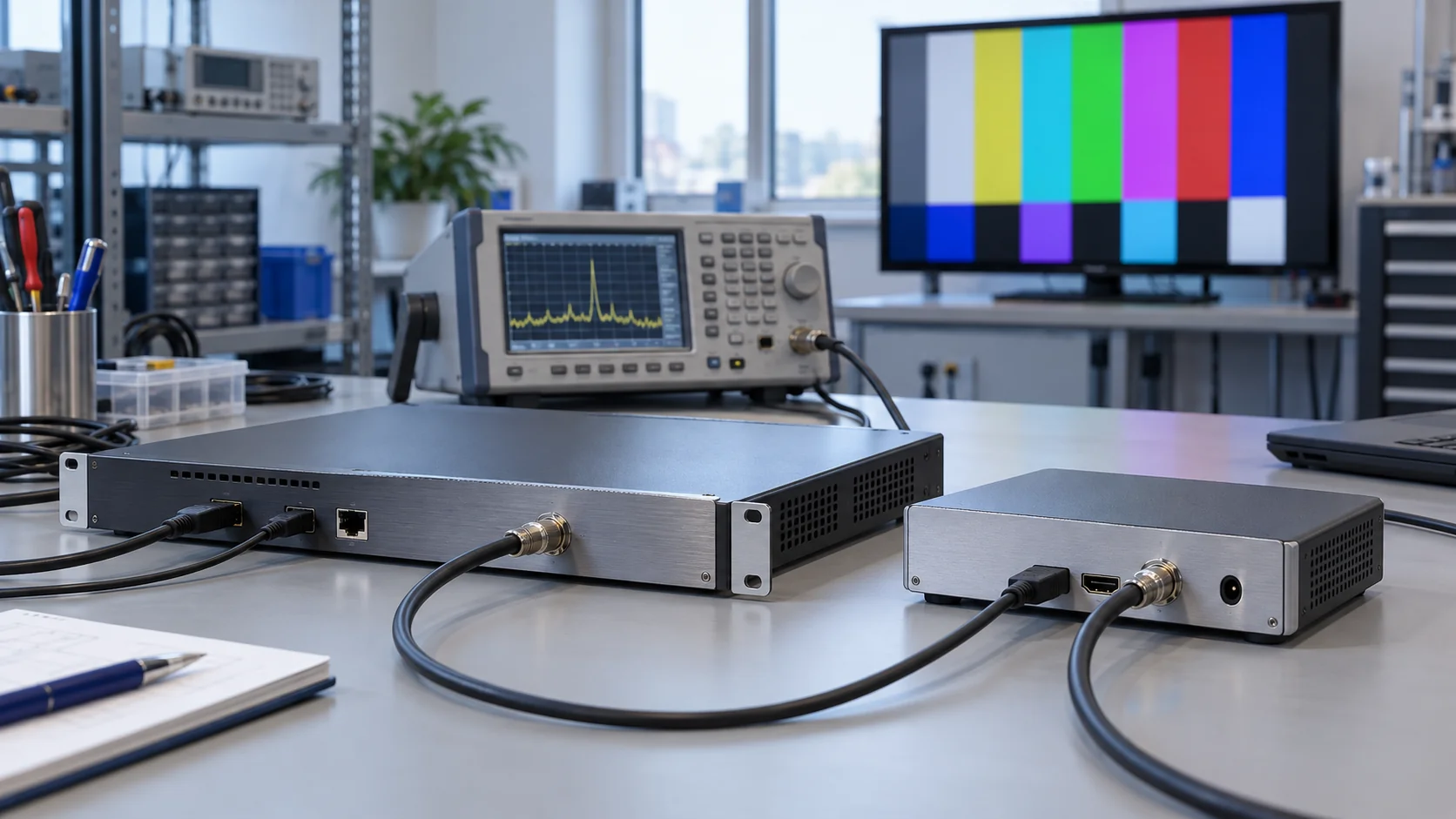
Output level describes signal strength. It does not by itself describe signal quality. A professional comparison should also examine modulation quality, errors, spectral behaviour and stability. The appropriate measurements depend on the selected RF standard and the analyser's supported mode.
Modulation error ratio (MER) indicates modulation accuracy. Bit error ratio (BER) describes errors at a stated point in the decoding process. Rohde & Schwarz discusses these measurement families in its DVB-T signal-quality application note. A single number without the test conditions or measurement definition is insufficient for comparing equipment.
Avoid an unsupported universal threshold
Do not copy one MER or BER limit into every project. Modulation mode, coding, receiver requirements and operating margin matter. Specify acceptance limits using the applicable system requirements and an agreed test method. State whether BER is measured before or after a correction stage, how long it is observed, and what instrument configuration is used.
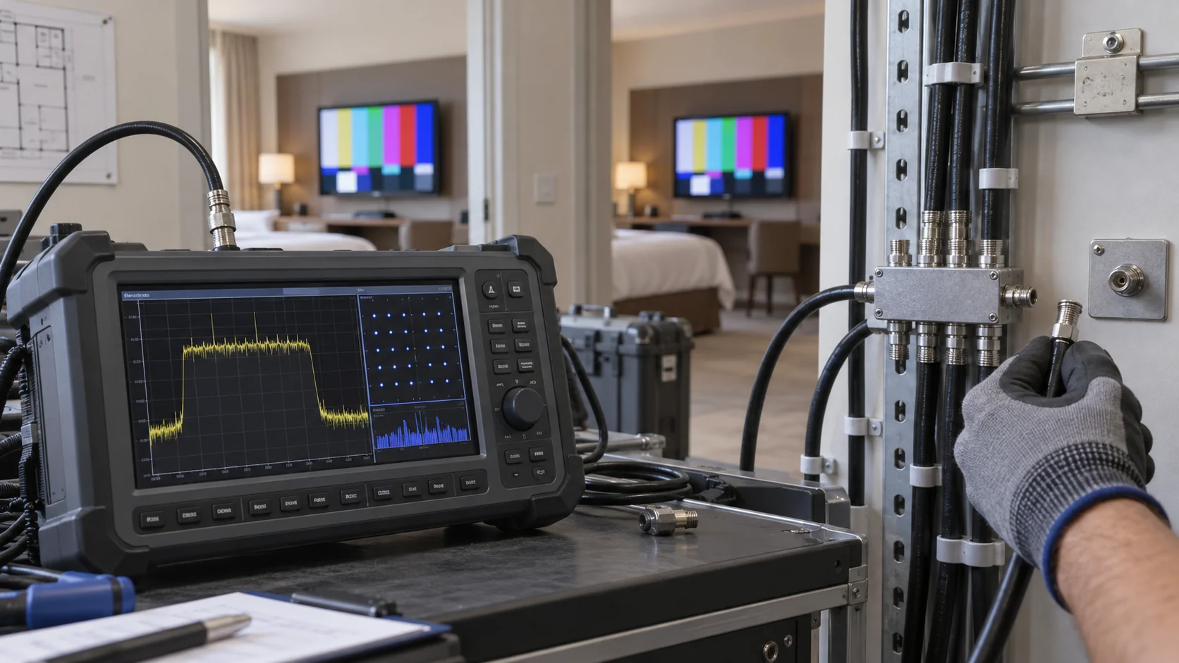
Measure a baseline at the modulator output, then compare relevant points after combining, amplification and distribution. This helps separate a device problem from degradation introduced elsewhere. Keep input levels within the analyser's appropriate range and use suitable attenuation where needed; an overloaded instrument can produce misleading results.
Request a test record for the quoted configuration, including firmware, active channels, output level and operating conditions. If the vendor provides only a typical value, ask what is guaranteed and how the acceptance test will verify it. Compare the same operating mode and workload rather than unrelated best-case laboratory figures.
Plan channels, output levels and the coax distribution path
A professional HDMI modulator comparison must account for the network receiving its output. Document RF frequency, channel bandwidth, modulation parameters and service identifiers. Check collisions with existing channels and confirm how the televisions scan and present the new services. Avoid choosing a channel solely because it appeared clear at one test point.
Evaluate the complete path through combiners, amplifiers, taps and outlets. Each part affects levels and may affect quality. The goal is a suitable signal at every required receiver, with practical operating margin. Maximum modulator output is not automatically the correct setting for the building.
Check both strong and weak receiving points
The nearest outlet can overload a receiver while a distant branch has insufficient signal. Test representative extremes, including branches with different cable routes or splitter arrangements. If adjustments are needed, consider distribution design and balancing rather than continually increasing a single output setting.
Document amplifier operating conditions with all intended carriers present. Adding channels changes aggregate loading, and a branch that works during a one-channel demonstration may behave differently under the full channel plan. Confirm the relevant pass criteria with the integrator and retain before-and-after readings.
When comparing quotes, identify who is responsible for coax surveys, channel planning, balancing and room testing. A headend-only quotation and a fully commissioned system are different scopes. Our Cable TV Solution for Hotels is the relevant commercial starting point for a property-wide review. Make the distribution work explicit before approving equipment quantities or a commissioning schedule.
Use a comparison matrix that exposes missing evidence
Use the same matrix for every shortlisted unit. Separate a supported feature from an operational requirement and from test evidence. “Yes” in a feature column is only a starting point: procurement needs to know the exact configuration, the conditions under which it works and any extra equipment or licence cost.
| Comparison item | Ask the supplier | Acceptance evidence |
|---|---|---|
| RF compatibility | Which standard and mode are included? | Reception on each installed TV family |
| Input and encoding | Which timings, codecs and audio formats work together? | Agreed source and receiver test profile |
| Simultaneous capacity | What is supported with every required channel active? | Full-load operation using the quoted configuration |
| RF quality | Which values are guaranteed and how are they measured? | Documented output and distribution measurements |
| Channel management | How are services named, ordered and updated? | Scan and channel-list checks on sample room TVs |
| Recovery | What happens after source or power loss? | Observed restart and signal-restoration behaviour |
| Lifecycle support | How are firmware, backups and replacements handled? | Handover records and an agreed support process |
Keep one column for exceptions and another for costs outside the unit price. Include modules, source receivers, distribution changes, commissioning, spares and shipping where relevant. Mark unknown values as unconfirmed rather than filling them with another model's specification.
Use mandatory compatibility requirements to screen proposals before comparing optional features. There is little value in scoring extra management functions on a unit that the installed televisions cannot receive. Once the mandatory items pass, compare operational convenience and delivered cost in the context of your property's staffing and service expectations.
The matrix should remain useful after purchasing. Link each accepted requirement to a saved configuration or test record, and record the responsible supplier or integrator. This makes later expansion and troubleshooting easier to assess without reconstructing the assumptions behind the original order.
Run a pilot test before purchasing the full system
A pilot test should reproduce the proposed signal path closely enough to expose integration problems. Use the intended HDMI source, modulator firmware, RF mode and representative room televisions. First establish a short, controlled baseline path, then move to representative outlets in the actual distribution network.
- Confirm the source: verify picture and sound directly on a known compatible display.
- Confirm encoding and RF: apply the agreed output profile and measure the modulator baseline.
- Scan every receiver family: verify service names, ordering, picture, sound and channel changes.
- Activate the full workload: test all purchased inputs and carriers concurrently.
- Exercise recovery: restart sources and equipment under agreed test conditions and record what restores automatically.
- Check distribution extremes: compare suitable measurement points and representative room outlets.
Set a test duration that reflects project risk and operating expectations. A short demonstration can confirm an initial connection, but it does not establish continuous performance across every branch or prove a universal reliability claim. Record ambient conditions, equipment versions and any interruptions during the observation period.
Measure what the guest experiences
Channel startup, picture continuity and audiovisual synchronisation matter alongside RF measurements. A receiver can show an apparently clean signal after it locks while still taking too long to open a service. Document these behaviours with a consistent method and agreed acceptance limits.
If a test fails, change one variable at a time. Preserve the known baseline and isolate source timing, encoding profile, RF settings and network effects in sequence. This provides useful evidence for the supplier and avoids a collection of undocumented adjustments that happen to work on one television.
Evaluate management, replacement and supplier support
For a hotel or commercial installation, equipment must remain practical after the installer leaves. Compare configuration backup, supported management interfaces, firmware update procedures and recovery steps. Confirm which information can be monitored and how the operator identifies a lost source or failed output.
Assess fault impact separately from advertised channel density. A larger chassis may reduce rack space and cabling while concentrating more services in one maintenance event. Smaller units can divide the affected services, but increase management and replacement work. The best arrangement depends on the property, the accepted outage impact and the available maintenance team.
Ask how a replacement is commissioned
Can the configuration be exported and restored to a compatible spare? Which settings remain tied to firmware or hardware variants? How are channel identifiers and output levels checked after a swap? Request the documented procedure, and practise it on a test unit where appropriate before handover.
Keep management access appropriately restricted and use the supported authentication and access methods. Remote support should follow the property's approved process. An RF distribution system does not eliminate the need to manage its administration interfaces securely, especially when control ports are connected to a broader network.
For procurement, distinguish warranty terms from practical service arrangements. Record replacement lead times, support contact details, fault evidence requirements and the scope of commissioning assistance. SOUKA product and solution pages can help shortlist equipment, but the final quotation should identify the exact supported configuration. Do not infer a capability across the whole range from one model's feature list.
Turn the comparison into an actionable quotation brief
Send each supplier the same source list, TV inventory, channel plan and acceptance matrix. Ask for a configuration-based quotation rather than a recommendation based only on the number of hotel rooms. Receiver count affects distribution design; it is not interchangeable with the number of programmes or encoding inputs.
Specify the initial workload and realistic expansion scenario. State which additions must be possible without replacing the receiving televisions or changing the RF standard. Ask the supplier to show where additional channels, modules, licences, network adjustments or rack capacity become necessary.
Separate mandatory and optional items
Mandatory requirements should cover signal compatibility, full-load operation, distribution acceptance and recovery. Optional requirements can cover preferred management interfaces, spare arrangements or additional outputs. This separation prevents a long feature list from obscuring the items that determine whether the system will function.
For a mixed or evolving property, compare coax delivery with an IPTV solution for hotels at the system level. The IPTV option involves different server, network and endpoint requirements; an HDMI modulator alone does not provide guest middleware or PMS integration. Keep that architectural decision distinct from selecting an RF unit within an accepted coax design.
Before issuing the purchase order, attach the accepted matrix and identify unresolved exceptions. Confirm who performs the pilot, who signs off room reception and which documentation must be delivered. A clear scope supports both fair pricing and a smoother commissioning handover, with fewer assumptions left for the engineer on site.
Related Products
Related Solutions
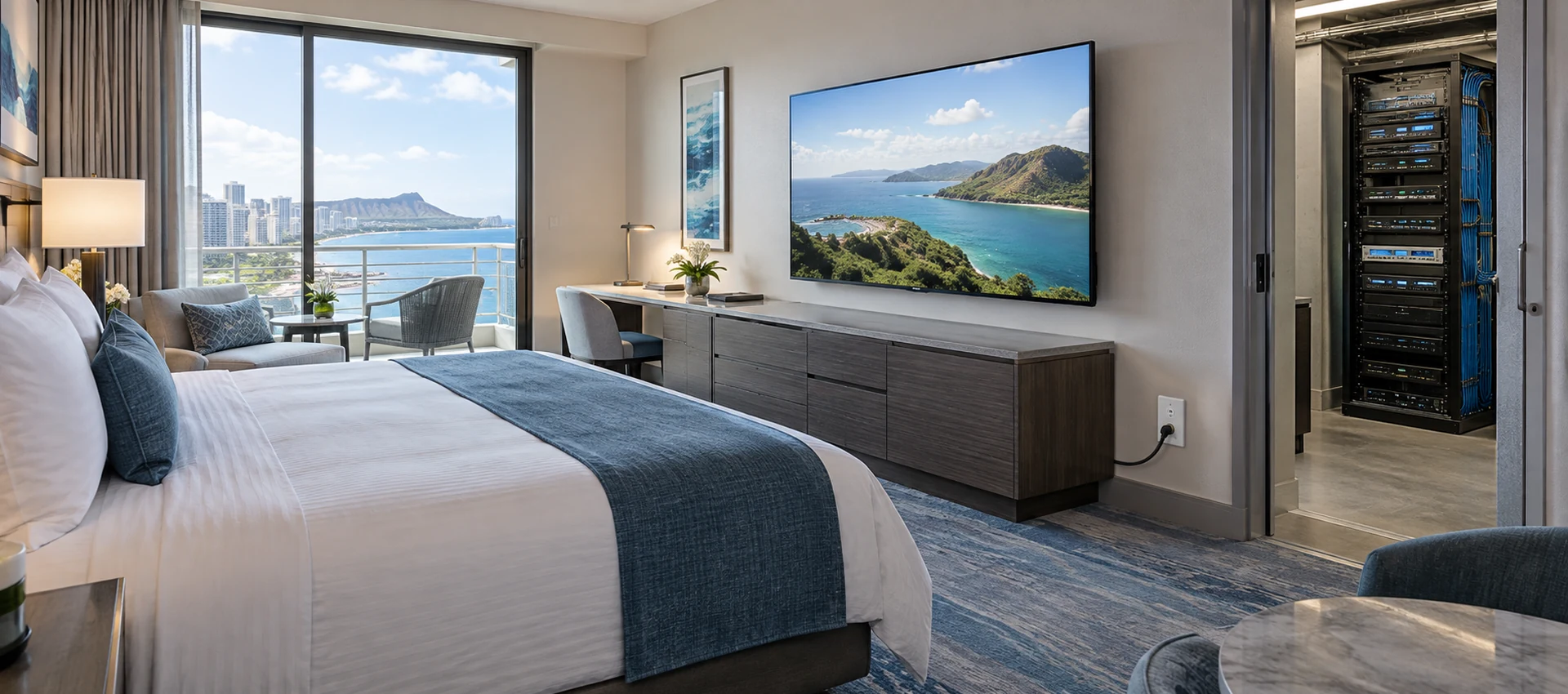
Cable TV Solution for Hotels
Deliver stable live television to every guest room without rebuilding the property network. SOUKA combines multi-source reception, high-density digital or analog modulation, RF combining, amplification, and centralized headend management for new hotels, phased renovations, and legacy coax upgrades.
Explore Solutions
IPTV Solution for Hotels
Deliver lag-free 4K live TV to every guest room, customize your interactive brand interface with zero coding, and automate database workflows. Our carrier-grade Linux streaming matrix bridges natively with global property management systems to eliminate integration friction and slash hardware deployment overhead.
Explore Solutions
Cable TV Solution for Hotels
Deliver stable live television to every guest room without rebuilding the property network. SOUKA combines multi-source reception, high-density digital or analog modulation, RF combining, amplification, and centralized headend management for new hotels, phased renovations, and legacy coax upgrades.
Explore Solutions
IPTV Solution for Hotels
Deliver lag-free 4K live TV to every guest room, customize your interactive brand interface with zero coding, and automate database workflows. Our carrier-grade Linux streaming matrix bridges natively with global property management systems to eliminate integration friction and slash hardware deployment overhead.
Explore SolutionsFrequently Asked Questions
Conclusion: compare configurations and acceptance evidence
To compare HDMI modulators for professional use effectively, verify the complete source-to-television path. Match the RF standard and encoding profile to the actual receivers, document the channel plan, measure quality at agreed points and test the full workload. Assess restart behaviour and maintenance alongside normal playback.
Use the same requirements and test conditions for every proposal. Keep specifications, supported operating combinations and observed results separate, and resolve exceptions before ordering. The resulting comparison is useful for procurement, commissioning and later expansion because it records what the installation actually needs.
Contact SOUKA for a project-specific modulator configuration review with your HDMI source list, television model numbers, existing coax layout and required channels. Include the acceptance matrix so that the quotation can address compatibility, equipment scope and site testing together.