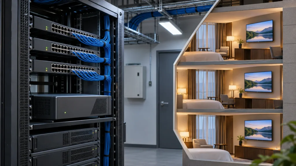
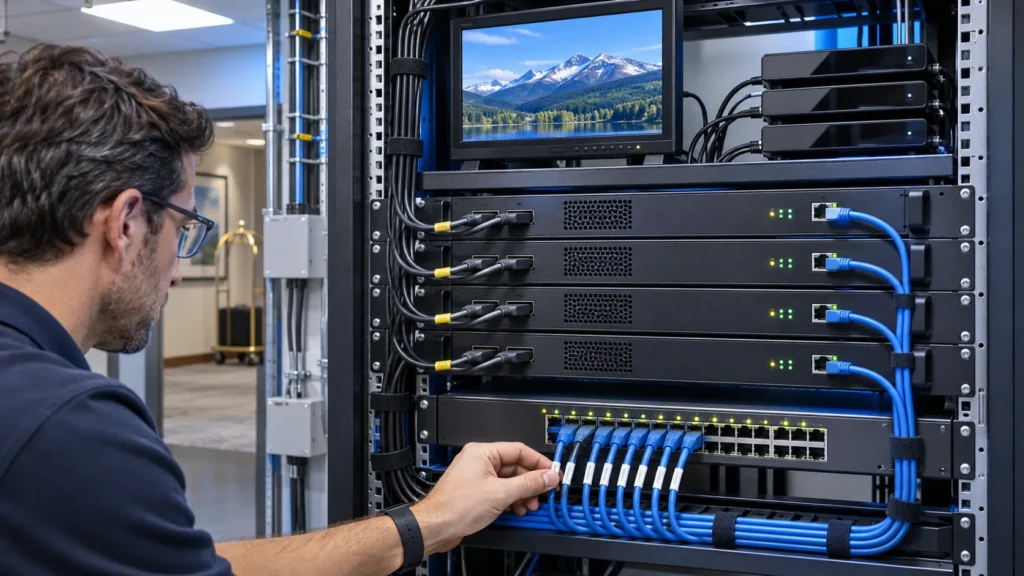
A fiber optic network switch connects hotel IPTV equipment across optical Ethernet links, but a fiber port alone does not guarantee stable television. The switch, transceivers, installed fiber, multicast settings and room receivers must work as one system. This guide helps hotel engineers and system integrators turn a network sketch into a purchasing specification, a capacity calculation and a practical acceptance test.
Where a fiber optic network switch fits in hotel IPTV
Choose the switch for the job at its location: carrying the complete headend output, aggregating several floors, or serving a group of guest rooms. These positions have different port counts, traffic patterns and recovery needs. Start with the service path, then select hardware that supports that path under normal operation and a planned failure.
A typical active Ethernet layout runs from the IPTV source equipment to a central switch, through optical uplinks to floor switches, and finally through suitable room connections to televisions or set-top boxes. Fiber can extend the backbone between buildings or communication rooms. The final room connection does not automatically become optical just because the backbone uses fiber.
| Equipment | Main task | Do not assume |
|---|---|---|
| Managed Ethernet switch with optical ports | Forwards Ethernet traffic and applies supported network controls | Every optical port supports every transceiver or multicast feature |
| Media converter | Changes the physical medium for a compatible Ethernet link | It provides the management functions of a switch |
| PON OLT and ONU/ONT | Operate a compatible passive optical access system | A standard Ethernet SFP can replace an OLT or ONU |
| CATV optical transmitter and receiver | Carry an RF television distribution signal optically | The optical link is an Ethernet IPTV switching link |
These distinctions matter when a proposal uses the phrase all-optical network. Ask which architecture it means, where active equipment sits, and how the television service reaches each room. Use the SOUKA engineering resources to connect the network discussion with the wider television design, then compare the topology with the hotel IPTV solution.
Give each link a name on the drawing. Identify its two endpoints, the services crossing it and the owner responsible for configuration. This simple schedule makes later quotations and fault reports much easier to compare.

Survey the installed fiber before choosing the optics
The installed cable plant defines which optical links are practical. Record the fiber type, actual route length, available strands, patch-panel interfaces and test results before ordering switches or modules. A familiar connector shape or jacket color is not enough to identify a usable link.
For an existing hotel, request the as-built cable schedule and inspect both ends of each proposed route. Include patch leads, intermediate panels, splices and any passive components. A short distance between two rooms can still involve a longer cable route and several connections. An undocumented route should remain a survey item rather than becoming an assumed saving in the quotation.
Match the complete optical link
Check the switch model, exact port, software support, module type, line rate, fiber specification, wavelength, connector and supported reach as a combination. Both ends must be compatible. For single-fiber bidirectional optics, use the complementary transmit/receive pairing specified by the supplier.
Cisco’s fiber-link troubleshooting guidance explains why port and transceiver compatibility, matching speed, fiber mode and connector details must be checked together. Its commands and compatibility matrix apply to the relevant Cisco equipment; use the selected vendor’s documentation for other switches.
An SFP-shaped opening does not establish the operating speed. Likewise, an SFP+ module does not make an unsupported port run at a higher rate. Obtain written confirmation for the exact hardware and software combination, especially where a contractor proposes substitute optics.
- Record spare fiber pairs and whether they follow the same physical route.
- List patch-panel and module connector requirements separately.
- Specify how optics, patch leads and approved substitutes will be labeled.
- Check cabinet temperature, airflow, power availability and access for maintenance.
Keep uncertain items visible in the bill of materials. An alternate module is useful only when the installer knows when to use it, what it replaces and how to verify it. Do not turn a preliminary cable survey into an unconditional compatibility promise.
Size each uplink for the traffic that actually crosses it
Calculate traffic at each bottleneck instead of multiplying the room count by an arbitrary bitrate. Multicast, unicast and on-demand services place different loads on a fiber uplink. Allow separately for other services, protocol overhead, growth and the traffic remaining after a link or switch fails.
For multicast television, count the distinct streams that must cross the link. Several receivers watching the same multicast group do not normally require a separate upstream copy for each receiver on that link. The worst case can still approach the full channel lineup when viewers select many different services.
For unicast delivery, count simultaneous sessions and their planned rates. VOD, casting and guest internet can add separate traffic. Where the same infrastructure carries more than television, obtain the other service owners’ requirements rather than treating them as unused capacity.
A hypothetical calculation
Assume a floor may need 36 distinct multicast channels at a planned 8 Mb/s each. The television payload is 36 × 8 = 288 Mb/s. If the same link also carries 20 unicast sessions at 6 Mb/s, those add 120 Mb/s. The combined example payload is 408 Mb/s, before overhead and other traffic.
| Illustrative load | Calculation | Payload |
|---|---|---|
| Distinct multicast channels | 36 × 8 Mb/s | 288 Mb/s |
| Concurrent unicast sessions | 20 × 6 Mb/s | 120 Mb/s |
| Combined example | 288 + 120 Mb/s | 408 Mb/s |
These are planning assumptions, not SOUKA product measurements or a recommended bitrate. A nominal 1 Gb/s link is not automatically acceptable because the arithmetic is below its label. Review peaks, queues, uplink sharing and the agreed operating margin, then test the selected design with representative traffic.
Recalculate the same path in its failure state. If two uplinks normally share traffic but only one survives, the remaining path must support the defined service. The IPTV distribution design guide covers the wider network choices behind this link-by-link calculation.
Specify multicast behavior, not just an IGMP checkbox
A switch must forward the required television groups reliably and contain traffic where it is not needed. Confirm the receivers’ membership behavior, the VLAN design, the query function and the handling of unknown groups. A data-sheet entry reading “IGMP supported” is only a starting point.
RFC 4541’s IGMP and MLD snooping considerations describe how snooping switches use membership information when forwarding multicast. The document is guidance for this behavior, not a certification that an individual switch works with every television platform. IPv6 multicast uses MLD rather than IGMP, so identify the addressing and membership protocols actually required.
Agree responsibilities for every television VLAN
Name the device providing queries where they are required, the upstream multicast-router-facing connections and the paths that must carry reports and streams. If television traffic crosses routed boundaries, the routed multicast design also needs an owner. Layer 2 snooping alone does not create that routed path.
Ask what happens when a receiver joins, changes channels, sleeps, restarts or leaves a group. Test the real TV and set-top-box models. Fast-leave behavior needs particular care when several receivers share one downstream port through another device; an assumption that there is only one listener can interrupt the others.
- Verify the documented group and membership capacity for the selected switch.
- Check the supported protocol versions against the source and receiver requirements.
- Observe traffic on a port with no interested receiver.
- Test channel changes while other rooms continue viewing.
- Confirm membership recovery after a querier or uplink interruption.
Save the tested configuration and software versions with the handover package. A screenshot of the snooping setting is not enough evidence of correct behavior. Keep receiver compatibility and service recovery within the same acceptance plan used for the hotel IPTV streaming service.
Check optical power and maintain an evidence trail
A fiber link needs both adequate optical margin and clean physical connections. Compare the installed path’s measured loss with its design allowance, then check receive levels against the actual transceiver limits. A green link indicator does not replace cable-plant testing.
The Fiber Optic Association’s loss-budget guidance separates the cable plant’s expected loss from the optical power budget supported by the equipment. Include the installed components in the calculation and compare the result with measurements made using an appropriate light source and power meter. Use OTDR evidence where needed to investigate individual events along the route.
Keep the limits tied to the selected module
Record the permitted transmit and receive ranges for the exact optics. Excessive loss is one risk, but a short connection can also require attention to the receiver’s upper power limit. Do not prescribe an attenuator from distance alone; follow the module documentation and the measured conditions.
Where the switch and optics support digital optical monitoring, retain baseline transmit power, receive power, temperature and alarms. These readings help compare later incidents with commissioning conditions. They supplement the installation test record; they do not automatically certify the complete cable plant.
Inspect and clean connectors using the appropriate tools and safe procedures before reconnection. Never look into an optical port or fiber. Keep unused connections capped, respect cable handling limits, and avoid tight bends or unsupported patch leads inside crowded cabinets.
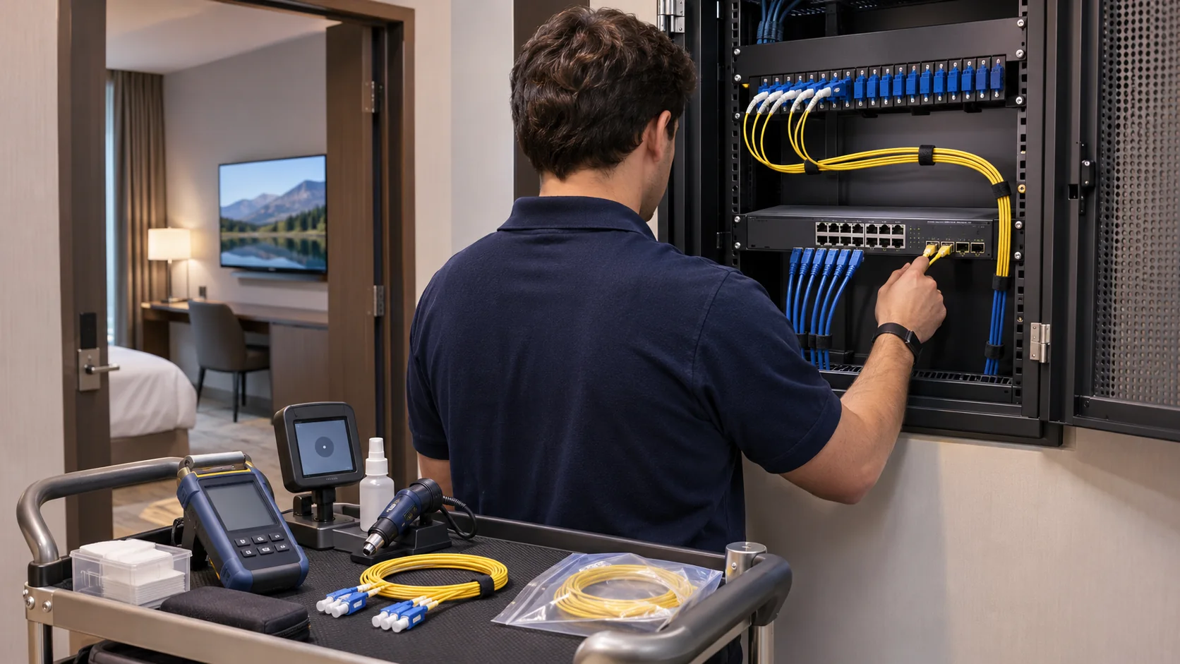
A useful handover record associates each measurement with the route, strand, panel port, module and switch interface. Store the test method and date as well. Without those identifiers, a good-looking result may describe a different link from the one carrying the guest’s picture.
Design recovery around the hotel’s operating limits
Redundancy is useful only when it preserves the intended television service during a defined failure. Specify which faults the hotel must tolerate, how much service interruption is acceptable and who can restore the system. Then verify the complete path, including power and configuration.
Two fiber pairs in one damaged cable do not provide route diversity. Two switches on the same failed power source may disappear together. Draw these shared dependencies explicitly before describing a proposal as resilient. The same review should include the headend, server, aggregation, floor equipment and management access.
Test service recovery as well as link recovery
An interface becoming active does not prove that all receivers have resumed viewing. A recovery test should observe the forwarding path, multicast membership and actual picture and sound. Agree how to time the interruption and which rooms or test receivers are representative.
Record the normal configuration before testing. During an approved maintenance window, simulate only the failures covered by the plan, one at a time. Restore the original state and confirm there are no new errors or unexpected forwarding paths. Avoid experimenting on an occupied hotel’s live network without an agreed operational procedure.
- Identify the designated spare module, patch lead and switch configuration.
- Confirm what the remaining uplink carries when its partner is unavailable.
- Keep an accessible configuration backup and a clear rollback procedure.
- Assign responsibility for investigating an optical fault versus a stream or receiver fault.
The hotel IPTV procurement guide can help define those boundaries between vendors. In the switch specification, request evidence for the chosen topology and software features rather than accepting a general claim of seamless failover.
Commission the fiber optic network switch with real receivers
Acceptance should prove the optical path, network behavior and television experience together. Use the agreed source lineup, several representative receivers and the expected concurrent traffic. Define pass conditions before the test, including allowed interruptions and the evidence to retain.
| Test | Observe | Keep as evidence |
|---|---|---|
| Physical link | Approved optics, negotiated rate, measured loss and receive levels | Route IDs, module details and optical reports |
| Normal viewing | Picture, sound and channel changes on representative terminals | Receiver models, source settings and test results |
| Busy-period traffic | Link utilization, drops, errors and service continuity | Traffic assumptions and interface counters |
| Membership behavior | Joins, leaves, sleeping terminals and uninterested ports | Group state and observed forwarding |
| Defined failure | Remaining-path load and actual viewing recovery | Fault introduced, timing and restored state |
Separate a transport fault from a source fault
If all rooms lose the same channel, compare the source output with the signal arriving at a known-good receiver. If only one floor fails, compare the floor uplink and local switching state. If a single terminal fails, check its connection and compatibility before changing the whole network. These comparisons guide investigation; they are not proof of the cause by themselves.
Monitor errors over the agreed test period instead of recording only a single counter reading. Note when counters were cleared and whether traffic changed. Repeat the relevant viewing test after replacing a module or applying a configuration change, so the record connects the intervention with the observed outcome.
Retain the final topology, firmware versions, configuration export, port schedule and unresolved exceptions. The person receiving the system should be able to identify a faulty link without reconstructing the installer’s assumptions from memory.
Build a quotation that includes the entire working link
A comparable quotation identifies the switch, optical components, installed-link assumptions, configuration work and acceptance scope. Ask suppliers to separate confirmed items from survey-dependent allowances. This prevents a low equipment price from hiding the work needed to deliver a usable television service.
List every required access and uplink port, the rates needed in normal and failure states, and the multicast functions that will be tested. Include software or license requirements where applicable. For each fiber connection, identify compatible modules at both ends, patch leads, panel interfaces, spare parts and the person responsible for optical testing.
Define the boundary with the IPTV equipment supplier
Supply the channel schedule, encoding profiles, transport methods, VLAN plan and receiver list to both the television and network teams. Agree which team provides sample streams, configures memberships and checks viewing. A successful Ethernet test alone does not establish compatibility between an encoder and every room television.
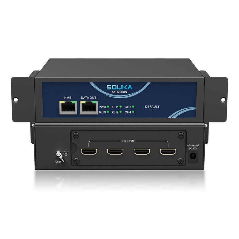
When reviewing a SOUKA television proposal, request the model-specific source, server and receiver requirements needed by the network designer. Confirm the switch and optics as a separate, documented part of the complete project. Do not infer a switch specification from an IPTV server’s Ethernet connector or from a generic system diagram.
- Attach the link schedule and verified fiber survey.
- State the service load assumptions and growth allowance.
- Require exact switch, software and transceiver part numbers.
- Include installation, configuration and agreed acceptance evidence.
- Record spares, support responsibilities and a documented change process.
Review exceptions before comparing totals. A quotation that excludes optics or leaves multicast configuration to another party can still be valid, but those exclusions must appear in the project scope. Award the work against a defined result rather than a port-count headline.
Related Products
Related Solutions
IPTV Solution for Hotels
Deliver lag-free 4K live TV to every guest room, customize your interactive brand interface with zero coding, and automate database workflows. Our carrier-grade Linux streaming matrix bridges natively with global property management systems to eliminate integration friction and slash hardware deployment overhead.
Explore Solutions
IPTV Solution for Hotels
Deliver lag-free 4K live TV to every guest room, customize your interactive brand interface with zero coding, and automate database workflows. Our carrier-grade Linux streaming matrix bridges natively with global property management systems to eliminate integration friction and slash hardware deployment overhead.
Explore SolutionsFrequently Asked Questions
Conclusion
The right fiber optic network switch is the one that fits the installed cable plant, carries the planned television traffic, manages multicast correctly and passes the hotel’s recovery tests. Confirm the exact optical combination, measure the working links and retain a configuration and acceptance record that the operations team can use.
For a coordinated television design, send SOUKA your room count, channel lineup, receiver models and proposed fiber topology. A project-specific review can establish the IPTV equipment requirements and identify the network information still needed before the final bill of materials is agreed.