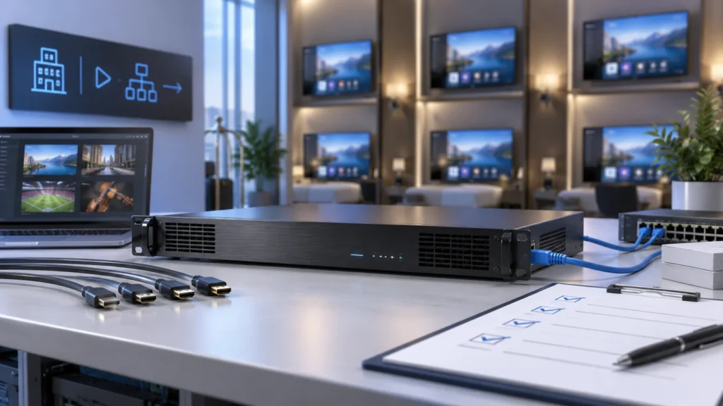
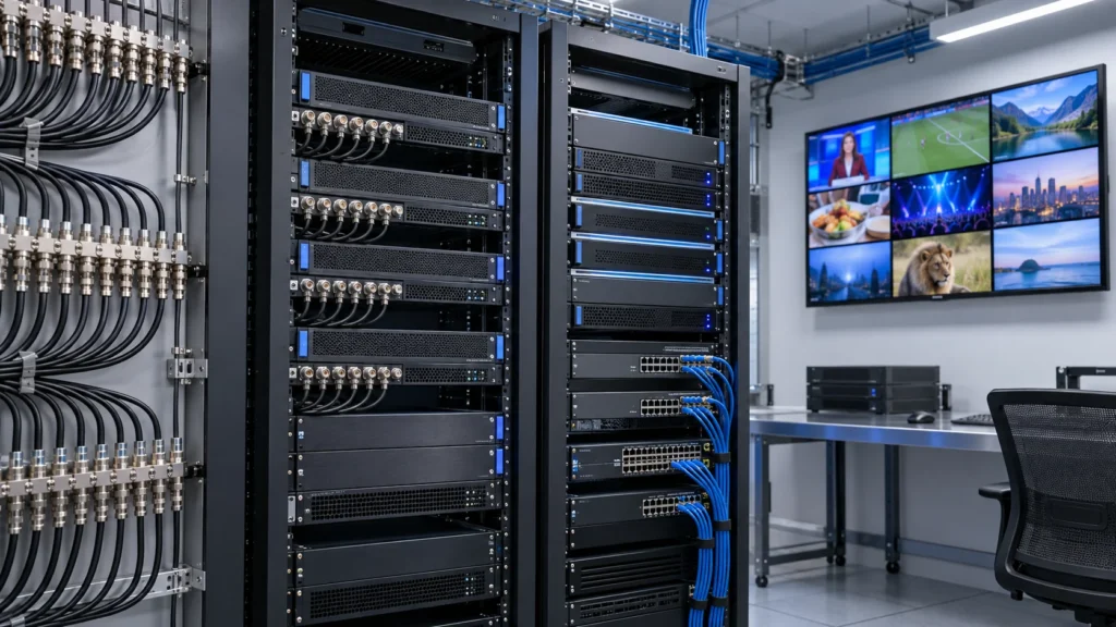
What should an HD IPTV headend encoder deliver?
An HD IPTV headend encoder converts a compatible live audio and video input into compressed streams for an IPTV service. In a hotel, its job starts at the source connection and ends at an agreed IP output. The equipment specification should identify the channel, input timing, video and audio format, stream address and receiver that will prove this path works.
Begin with a channel schedule before comparing equipment. Use the SOUKA IPTV streamer and encoder range to identify suitable hardware, then record what each source actually supplies. A satellite receiver with an HDMI output, an existing compressed IP feed and a local camera can require different processing paths even when they all appear in the same guest channel list.
This guide focuses on specifying and accepting the encoding stage. The IPTV headend architecture guide covers the wider system of receivers, gateways, middleware and distribution. Keep that wider drawing beside the encoder schedule so every input and output has an owner.
For each channel, assign a source identifier and its business purpose. Record the programme owner, connection type, expected operating hours, audio language, permitted distribution scope and guest endpoint. Add a decision for loss of input, such as an approved fallback slate or an operator alarm. This makes the design useful to both the installer and the person answering a guest complaint.
Use one representative channel as a pilot. A successful pilot should reproduce the planned source, encoder configuration, network handoff and room receiver. A demonstration using another source or a laptop player can help diagnosis, but acceptance should follow the actual hotel service path.
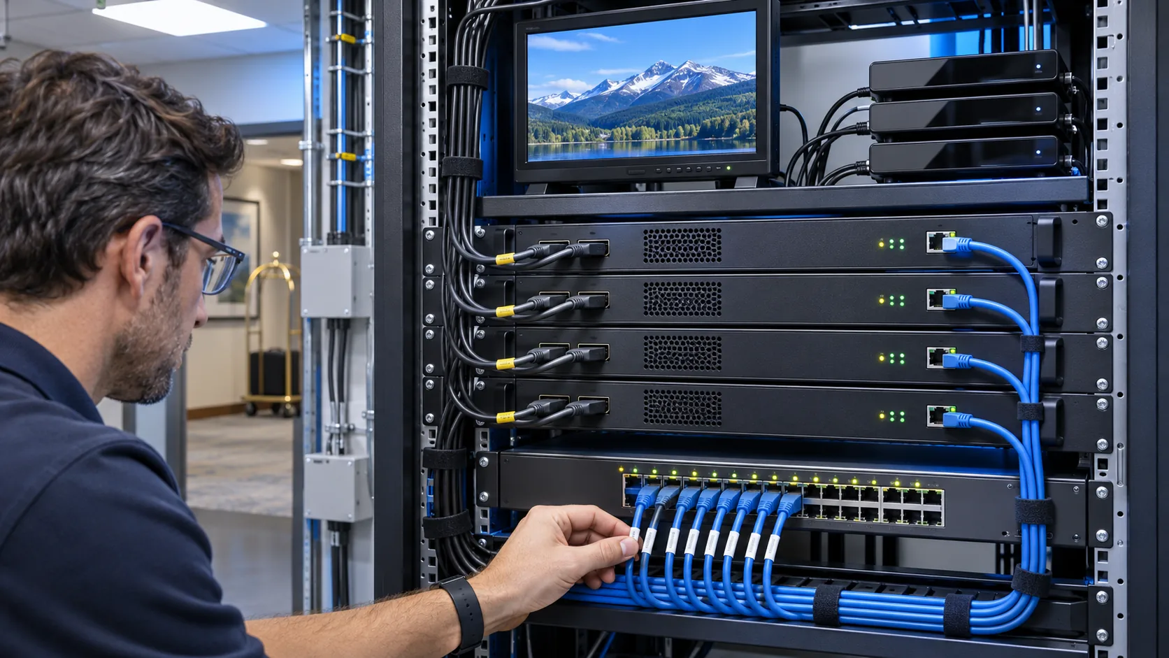
Map each source to the processing it actually needs
Separate source acquisition from video encoding when preparing the equipment list. A tuner gateway can receive a broadcast transport stream and forward selected services over IP. An HDMI encoder accepts a baseband source output and creates a compressed video stream. A transcoder changes an existing compressed stream into another encoding configuration. Check the offered model against the operation required for each channel.
| Source presented to the headend | Processing to assess | Evidence to request |
|---|---|---|
| HDMI from an approved receiver | HDMI acquisition and video/audio encoding | Actual source timing, supported input and a playable sample output |
| Existing compatible IP service | Relay, service selection or remultiplexing | Input transport, selected programme and unchanged codec compatibility |
| IP service with an unsupported codec | Transcoding if required | Concurrent workload at the proposed output settings |
| Broadcast RF feed | Tuning, authorised access and IP gateway processing | Broadcast standard, reception conditions and service permissions |
Document which organisation supplies and supports each source receiver. Channel subscriptions and distribution permissions belong in that handoff. Obtain confirmation that the intended commercial use and source connection are supported before placing the encoder order. If a source output is restricted, agree an authorised delivery method with its provider.
A mixed headend can use encoders and gateways together. Give both a common naming scheme while retaining their different failure checks. Loss of RF reception, loss of an HDMI input and loss of an IP output need separate alarm descriptions. That distinction makes a service fault easier to trace.
Keep spare inputs visible in the schedule. A connector left unused today may provide tomorrow's local information channel, but confirm whether the chassis also has the processing and output capacity for it. Physical sockets alone do not establish concurrent channel capacity.
Confirm input timing and audio before selecting a box
Specify the source timing as resolution, scan mode and frame rate. An input described as HD may mean 720p, 1080i or 1080p at different rates. The accepted input format and encoded output format can differ, so ask for both. Record any required deinterlacing or scaling and review motion on the actual display.
Use the source device's available output settings during the pilot. Check what happens after that source restarts, changes programme or loses its connection. EDID negotiation can affect the timing a source chooses. Save the tested source setting with the encoder profile instead of relying on an installer remembering how it was configured.
Audio needs its own acceptance line
Confirm whether the source carries stereo or multichannel audio, which audio codec will leave the encoder, and how the guest receiver decodes it. Test the intended language tracks and listen for channel imbalance, distortion or changing volume. Check lip synchronisation with speech as well as programme music.
Subtitles and accessibility services also require an explicit decision. Establish whether they are already visible in the video, carried as separate data, or provided by another part of the service. Confirm their availability after the proposed processing chain. A clear picture and sound do not demonstrate that every service feature survived.
Build the receiver sample from the hotel's real device estate. Include each important television or set-top-box family and its approved firmware. Where a legacy receiver needs a separate encoding profile, count that additional output in the equipment workload. Test power cycling and the normal start-up route into the guest television application.
Keep the pilot observations beside the source schedule. Record the exact configuration that passed and any exceptions that need a different source setting, player or encoder model.
Set a complete encoding profile for every channel
A usable encoder specification combines codec, profile, level, resolution, frame rate, rate control, target bitrate and audio settings. Add GOP or keyframe settings where the product exposes them. Two proposals with the same headline resolution can produce different workloads, motion quality and receiver behaviour.
Choose H.264 or H.265 using the actual decoding devices and content. Check fast motion, fine text and scene changes at the intended settings. Compare sample streams on the same receiver and display. The H.264 and H.265 hotel comparison explains the compatibility questions to resolve before choosing a codec.
Rate control also needs a clear definition. If the encoder offers constant bitrate, check whether the setting refers to video only or the complete service. If variable bitrate is offered, request the permitted peak and the conditions used to measure it. Size the network handoff from the complete transmitted service and verify the result with an independent capture.
Test a channel change with the chosen profile
Receiver buffering, keyframe availability, network joins and application behaviour can all contribute to channel acquisition time. Measure the complete change from one guest channel to another. Ask the supplier to show the settings used in its demonstration and repeat that test through the proposed network.
Keep low-delay requirements specific to the application. A lobby screen beside a live event may need a different delay budget from a normal guest room channel. Measure source-to-screen delay using one agreed method, then document the result and configuration. An encoder's processing delay is only one part of that total.
For a small pilot, save one approved reference profile and a sample stream. Expand to the full lineup only after the output works on every receiver family included in acceptance.
Specify the IP output and channel metadata together
Write down the output encapsulation, destination, port and programme structure for each service. UDP, RTP and HTTP-based delivery describe different parts of the delivery behaviour, so an interface list should identify the actual stream format used by the receiver. Confirm whether the handoff uses one single-programme transport stream per channel or a multi-programme stream requiring downstream selection.
For RTP delivery, verify the payload format and receiver support. RFC 3550 defines timing, sequence and reporting mechanisms used by RTP and RTCP. These mechanisms support delivery monitoring, while the network and receiving application still determine practical service quality.
For HEVC carried in RTP, RFC 7798 defines an HEVC payload format. Confirm the implementation used by both devices. A statement that two products support H.265 does not identify every transport and packetisation detail needed to make them interoperate.
Give service identifiers, names, audio selection and channel numbering an owner. Check which information the encoder inserts, which information another gateway supplies, and which fields the middleware or channel list assigns. Avoid depending on an undocumented default that could change after a replacement or factory reset.
Agree multicast addresses and port assignments with hotel IT, including how duplicate assignments will be prevented. Record the outgoing interface and any routing dependencies. Use the hotel IPTV distribution design guide for VLAN boundaries, switch forwarding and floor-level validation.
Finish the handoff document with an observable test. An operator should be able to identify one channel at the encoder output, verify its network destination and match it to the guest channel list. Save a short authorised capture or stream report with that channel's reference configuration.
Calculate capacity from the full concurrent workload
Count concurrent input channels and encoded outputs separately. A channel that needs a main HD output and a second lower-resolution output can create more work than a single-profile channel. Confirm that the offered hardware supports all requested streams together at the required codec, timing and bitrate settings.
A transparent planning example
Assume a project has 12 live channels, each with a measured total IP service rate of 6 Mb/s. One copy of each channel requires 12 × 6 = 72 Mb/s on the encoder-side path. If the designer chooses a provisional 20% allowance, the planning figure becomes 86.4 Mb/s. These are illustrative assumptions, and the allowance should be replaced by the project's measured overhead, peaks and growth requirement.
In that example, do not automatically multiply 72 Mb/s by every guest room when the encoder emits one multicast copy of each channel. Check where replication actually occurs. Conversely, if the device originates separate unicast sessions, count those output sessions and confirm the encoder's connection limits. Record the traffic direction and each link being assessed.
Recheck the calculation for any second encoding profile, preview stream, remote contribution or recording destination. Include the traffic the switch port actually carries. Verify that the negotiated port speed, switch configuration and downstream receiver design support the planned load with the agreed allowance.
The same calculation must survive the chosen failure scenario. If a standby device takes over, show which channels move, which settings it already holds and which network path then carries the traffic. The multi-channel encoder density and redundancy guide addresses the effect of grouping many channels in one chassis.
Ask the supplier for a simultaneous workload demonstration. A specification demonstrated one input at a time provides limited evidence for a fully populated headend running every channel continuously.
Use a bench test that can isolate the faulty stage
Prepare a repeatable bench test before equipment reaches the hotel. Start with a known source, one encoder output, a controlled switch path and an approved receiver. Save settings before changing them so a failed test can be reproduced. Assign a test identifier to each observation and keep source conditions consistent across suppliers.
| Test | What to observe | Record for handover |
|---|---|---|
| Source acquisition | Picture and audio at the agreed timing | Source model, output mode and encoder input status |
| Encoded service | Codec, bitrate, continuity and audio/video synchronisation | Encoding profile and stream analysis |
| Receiver playback | Channel changes, captions and start-up recovery | TV or box model, firmware and observed result |
| Concurrent load | Every requested channel and profile operating together | Workload, link traffic and fault observations |
| Recovery | Behaviour after a source or encoder restart | Alarm, recovery steps and remaining exceptions |
Use mixed content, including speech, sports-like motion, fine graphics and darker scenes. Agree which material is available for the test and compare the same sequence at each profile. Log visible problems alongside stream measurements. A clean bitrate graph alone cannot show that text is legible or audio follows the picture correctly.
When a fault appears, test progressively at the source output, directly after encoding, across the network and at the room receiver. Change one controlled variable at a time. Compare with the saved reference profile and note whether another channel on the same chassis is affected.
Set the trial duration and pass criteria with the project team. Include the normal busy period, expected source changes and relevant restart events. Keep the result as a signed test record with open exceptions and assigned owners, so installation does not begin with an unresolved compatibility issue.
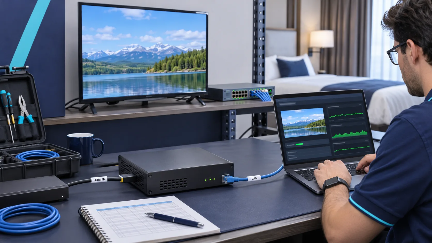
Plan maintenance and recovery around affected channels
Choose the failure domain deliberately. A dense encoder chassis can simplify rack wiring and management, while a chassis fault may affect several services together. Separate encoders distribute that exposure across units and introduce more devices to maintain. Compare both arrangements using the channels affected, available spares and the team's recovery procedure.
Keep the management interface on the intended network and grant access to the people responsible for the service. Confirm supported management methods, configuration export, account control and software maintenance with the supplier. Back up a known working configuration after commissioning and again after an approved change.
Make the spare operationally useful
A spare device should have a recorded software version, compatible power arrangements and a tested configuration. Identify the source cables that move during replacement and label both ends. If addresses or channel mappings need changing, write the sequence in the recovery guide and test it before handover.
Define alarms by their operational meaning. Input loss, missing output traffic and a receiver playback failure can point to different owners. Identify how the on-call team sees each condition and which reference checks it should perform. Confirm any required monitoring capability on the actual device instead of assuming it from a web management interface.
Inspect the installation conditions with the facilities team. Verify ventilation, accessible connectors, rack support, power loading and the proposed backup supply. Use the manufacturer's requirements for the selected model when planning clearance and operating conditions. Keep critical labels readable after the rack doors close.
During acceptance, have a second operator follow the written replacement procedure. Record any step that relies on an installer-specific laptop, forgotten login or unlabelled cable. The final handover should leave hotel staff able to identify the affected service and restore the tested configuration.
Compare model-specific evidence in the supplier proposal
Ask suppliers to return a completed channel schedule and test plan with the quotation. Include source timings, concurrent workloads, output formats, receiver samples, recovery requirements and installation conditions. Require each exception to be stated against the relevant line, with the offered model and software version identified.
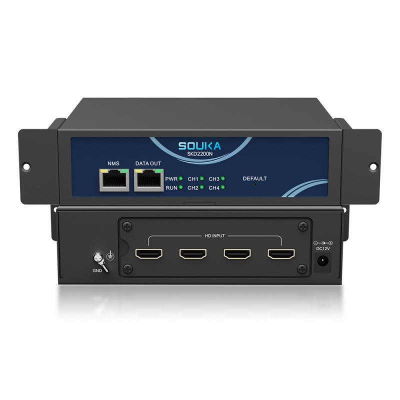
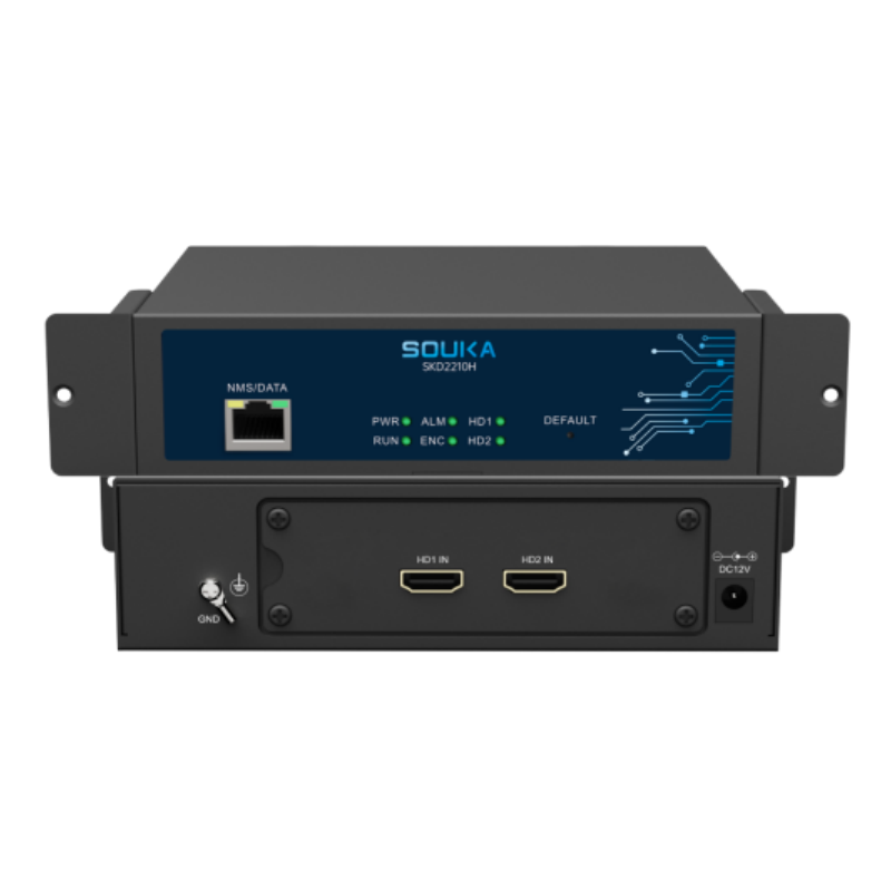
For an initial shortlist, the SOUKA SKD2210 four-channel HD encoder describes H.264 encoding with four SPTS outputs over UDP or RTP. The SKD2210H dual-channel HD encoder offers a smaller channel count. Check their individual input and output limits against the required schedule.
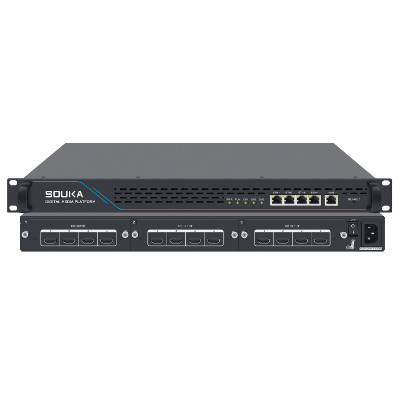
The SKD1510 H.265/H.264 multi-channel encoder provides another published configuration to assess for a larger lineup. Its current specification lists 12 HD inputs and up to 1080p30 encoding. Obtain confirmation of the exact configuration, concurrent profiles and receiver compatibility for the proposed project.
Compare cost using the same accepted service. Include modules, licences where applicable, spare hardware, commissioning support, source receivers, maintenance and required network work. Request a written explanation of what the quoted package includes. Keep optional future capacity separate from the configuration that must pass acceptance now.
Use the IPTV encoder buying guide for the wider purchasing checklist. For this headend order, finish with a short evidence package containing the final schedule, approved profiles, sample results, source permissions, network handoff, configuration backups and a recovery procedure.
A clear proposal lets the hotel identify how each service becomes a playable room channel. It also gives the supplier enough detail to recommend a different model when a requested timing, codec or workload falls outside the shortlisted hardware.
Related Products
Related Solutions
IPTV Solution for Hotels
Deliver lag-free 4K live TV to every guest room, customize your interactive brand interface with zero coding, and automate database workflows. Our carrier-grade Linux streaming matrix bridges natively with global property management systems to eliminate integration friction and slash hardware deployment overhead.
Explore Solutions
IPTV Solution for Hotels
Deliver lag-free 4K live TV to every guest room, customize your interactive brand interface with zero coding, and automate database workflows. Our carrier-grade Linux streaming matrix bridges natively with global property management systems to eliminate integration friction and slash hardware deployment overhead.
Explore SolutionsFrequently Asked Questions
Yes, in some applications.
If the IPTV streamer outputs standard IP streams, compatible TVs, set-top boxes, or media players may receive the streams directly.
However, for hotel IPTV projects requiring channel management, welcome pages, VOD, advertisements, room information, or centralized terminal management, an IPTV Server is normally used together with the IPTV headend.
Conclusion
Specify an HD IPTV headend encoder from the channels it must deliver. Confirm source timing, encoding profiles, concurrent outputs and playback on the hotel's approved receivers. Tie the purchase to a repeatable acceptance test and a recovery procedure that staff can follow.
Send SOUKA your source list, channel count, receiver models and network handoff for a headend encoder configuration review. The hotel IPTV solution provides the next step for fitting the encoder stage into the wider guest television service.