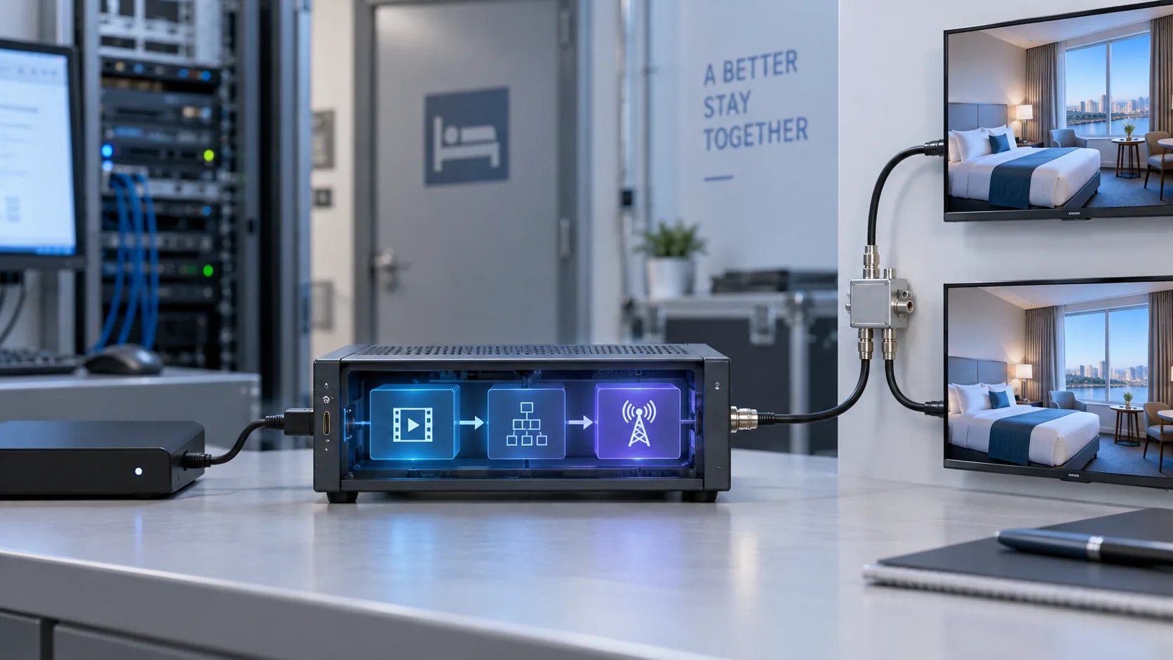
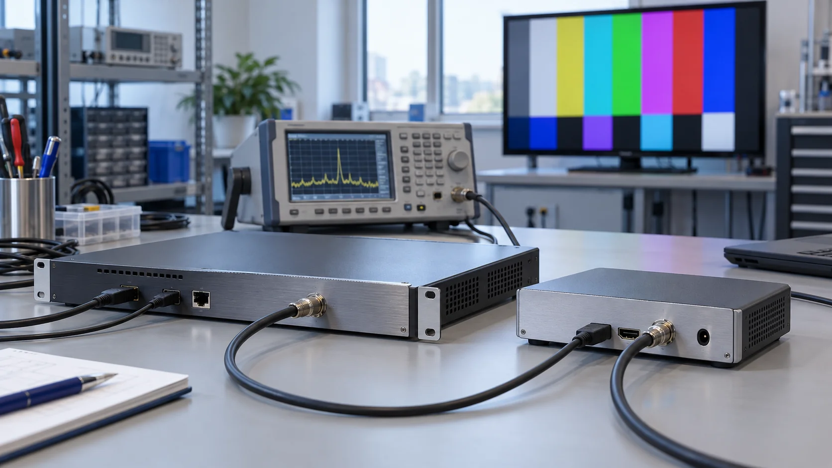
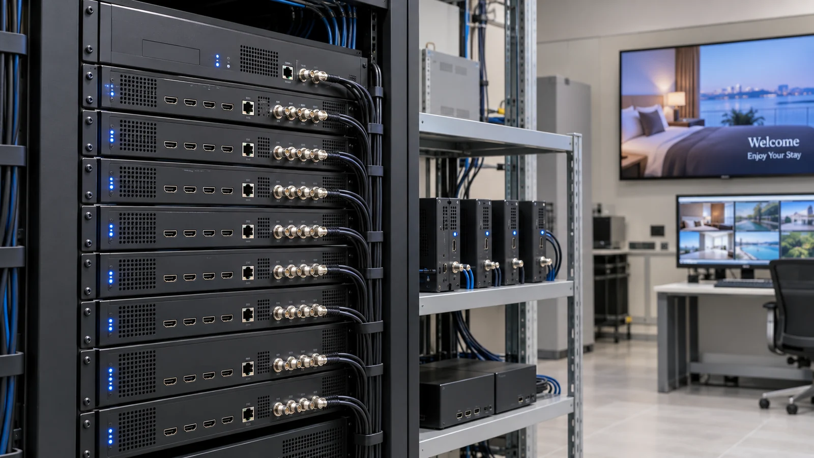
An HDMI to RF modulator can turn a centrally managed video source into a television service distributed over a hotel's coax network. Before ordering equipment, the project team needs a channel plan that connects each source to an encoded programme, an RF carrier and the channel guests actually select. Those are separate planning decisions.
This checklist helps hotel engineering teams, system integrators and B2B buyers prepare that plan without assuming that every HDMI input requires its own carrier or that every television handles the same signalling. Start with SOUKA's digital TV modulator range, then use the planning records below to define a configuration and a controlled installation test.
Separate HDMI inputs, programmes and RF carriers
The word “channel” can describe an input connector, a television programme, an RF transmission channel or a displayed channel number. A quotation that uses the word without a definition can hide a capacity mismatch. Write each quantity separately before comparing devices.
An HDMI source supplies one audio/video presentation to an encoder input. The encoded programme becomes a service in a transport stream. A carrier delivers a transport stream over an assigned RF frequency and bandwidth. Depending on equipment capabilities and available capacity, a stream can contain more than one programme.
Count the programmes guests must select independently
A welcome player and three independently selectable feeds create four source requirements. A source that changes between two videos on a schedule remains one simultaneous presentation. Conversely, a distribution device cannot create independently selectable channels from several programmes that arrive only as one preselected HDMI picture.
Document simultaneous operation, including sources needed during events or overnight. Distinguish installed inputs from licensed, enabled and tested encoding capacity. Ask whether output modes share resources and whether the proposed combination works with every required input active.
Keep the equipment-layout decision separate. The single-channel and multi-channel HDMI modulator guide explains chassis and maintenance tradeoffs. This article's planning unit is the service record: which source reaches which receiver, through which carrier, with which identity.
Build a receiver matrix before choosing the RF standard
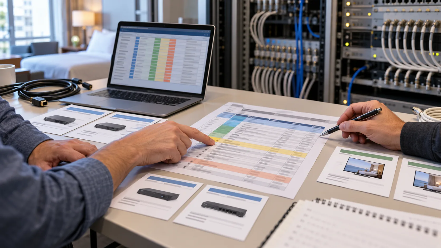
List the actual television and set-top-box models that must receive the service. Include full model numbers, regional variants, firmware and the operating mode used in the property. A country or screen-resolution label does not establish the receiver's RF and decoding capabilities.
Confirm the required transmission system, such as DVB-T, DVB-C, ATSC 1.0 or ISDB-T, and its specific supported mode. QAM is a modulation term used in different systems; a QAM label does not make all cable formats interchangeable. Confirm the intended system or annex with the equipment supplier and receiver documentation.
Test tuning and decoding as separate requirements
A television can lock onto an RF carrier yet fail to decode the selected video or audio format. Record codec, profile, resolution, frame rate and sound requirements alongside the tuner information. Include older televisions retained during phased refurbishment, not only a newly purchased sample.
Document whether guests use the television tuner directly or a dedicated receiver. If a box performs decoding, its capabilities govern that stage. The screen's HDMI input then has a different role from the RF input of a television receiving the carrier directly.
Use the ATSC hotel TV compatibility guide when ATSC is proposed. For mixed fleets, build a small representative test group before approving one headend profile. Mark untested receiver families as unresolved rather than extending a successful result to the entire hotel.
Assign a test outcome to each matrix row: accepted, accepted with a documented setting, or unresolved. Include the person who checked it and the configuration revision used. This prevents an older television from being silently excluded when the room count is summarized. If replacement receivers are proposed, include their quantity, installation work and support responsibilities in the quotation rather than treating them as an incidental accessory.
Define each source and its permitted distribution path
For every HDMI input, record the source owner, device model, output timing, audio format and required operating hours. A programme receiver, signage player and meeting-room feed may all provide HDMI while requiring different handling after restart or signal loss.
Confirm that the proposed distribution is authorized. Source protection, programme rights and commercial agreements are separate from technical signal conversion. Do not assume that a modulator bypasses HDCP or grants permission to redistribute subscribed content to guest rooms.
Specify behaviour when the source is unavailable
Decide what operators should see when a source stops: an alarm, a documented loss-of-signal state or an approved replacement screen, if the selected equipment supports it. Verify the actual behaviour during the pilot. Do not rely on an untested feature to keep a welcome channel available.
Keep a known-good source setting and a short reference connection. If the distributed programme later fails, compare that source with the saved baseline before changing RF parameters. The high definition RF modulator signal-flow guide provides a separate stage-by-stage fault-isolation method.
Also record who may change the source output. A player update that changes resolution or sound can disrupt an otherwise unchanged channel plan. Put source changes into the same maintenance process as headend changes so that a restart does not become an undocumented reconfiguration.
Allocate transport capacity with explicit assumptions
A multi-input HDMI-to-RF encoder-modulator has several capacity limits. Check simultaneous input processing, encoding resources, transport capacity and carrier availability independently. An unused connector or a spare frequency does not prove that the complete operating combination is supported.
Begin with the usable transport capacity for the exact RF standard and configured mode. Then budget video, audio, signalling and operational headroom. Obtain the relevant capacity and rate-control behaviour from the supplier rather than copying a generic maximum from another modulation mode.
A planning example, not a product specification
Assume, solely for a worksheet example, a usable transport capacity of 20 Mbit/s. Three services each reserve 5 Mbit/s for video and 0.2 Mbit/s for audio. Add an assumed 1 Mbit/s allowance for other transport requirements and 2 Mbit/s of reserved headroom. The planning total is 3 × 5.2 + 1 + 2 = 18.6 Mbit/s.
Under those assumptions, adding a fourth identical service raises the total to 23.8 Mbit/s and exceeds the assumed capacity. Having a fourth HDMI connector does not fix that budget. The team must review encoding requirements, service grouping or additional carrier resources without sacrificing receiver compatibility.
These numbers demonstrate the method only. They are not a recommended encoding rate, a measured overhead, a standard carrier capacity or a capability claim for any SOUKA model. Actual transport overhead and operating margin must be checked for the intended configuration.
For variable-rate encoding, confirm how peaks are bounded and how the equipment handles aggregate demand. Test representative motion, text and audio with all intended services active. A static welcome image alone cannot establish acceptable quality for a full entertainment lineup.
Survey the existing RF spectrum before assigning frequencies
Obtain the current channel plan and survey the installed network before selecting output frequencies. Identify existing broadcast feeds, analog carriers, private channels, occupied bands and any shared services. A frequency that looks unused in one receiver's channel list may still carry a signal.
Record channel centre frequency, bandwidth, RF system and relevant mode settings explicitly. Channel numbers can refer to different frequency plans, so a number without a system and frequency is an ambiguous installation instruction. Use consistent units throughout the headend and test records.
Check the whole distribution path
Review combiners, splitters, taps, amplifiers, cable routes and room outlets. Their operating range and losses constrain where new carriers can be placed. An amplifier with insufficient usable bandwidth cannot be corrected by changing a displayed channel number.
Measure the intended lineup with all carriers active. Combining more signals changes aggregate loading, while nearest and farthest outlets can present different reception conditions. Establish suitable levels and quality criteria with the integrator instead of setting every modulator to maximum output.
Do not connect a privately generated signal to a provider feed or a radiating antenna without an approved design. Keep source isolation and the boundaries of the property's distribution system explicit. The Cable TV Solution for Hotels is the relevant starting point for discussing the existing coax plant, combining arrangement and commissioning scope.
Keep service identity separate from the displayed number
After RF allocation, define how each programme is identified and presented to the television. Record programme or service identifiers, names and relevant transport or network identifiers using the fields supported by the selected system. Treat frequency and service metadata as connected records, not interchangeable settings.
For ATSC systems, the ATSC A/65 PSIP specification defines signalling tables carried in the transport stream, including information used for virtual-channel presentation. For DVB, DVB service discovery and metadata describes how service information helps receivers identify and select services. Neither reference establishes that every hospitality television applies identical channel ordering.
Verify how the installed televisions build their lineup
A requested logical or virtual number is not a universal guarantee of remote-control behaviour. Receiver software, country settings, scan mode and hospitality channel management can affect the result. Ask which numbering mechanism the equipment supports, then confirm it on every representative receiver family.
Avoid duplicate identifiers or conflicting displayed numbers within the intended receiver environment. The permitted values and required relationships depend on the system. Do not invent one universal numbering scheme for ATSC, DVB and other standards. Preserve the identifiers of working services unless a documented change is necessary.
Test rescanning, channel-list restoration and power recovery. A receiver with cached data can behave differently from a factory-reset test set. Record both an upgrade path from the existing lineup and a clean-scan result so that commissioning instructions cover the actual televisions already in rooms.
Use one controlled channel-plan worksheet
Keep the approved plan in one controlled record rather than separate source, frequency and remote-control lists that drift apart. Each service should be traceable to its input, carrier assignment, receiving requirement and maintenance owner. The following field groups form a practical starting template.
| Record group | What to include | Approval evidence |
|---|---|---|
| Source and rights | Device, input, format, owner, permitted use | Stable input and authorized distribution |
| Encoding and capacity | Video/audio settings, rate budget, service grouping | Full-load test in the quoted configuration |
| RF assignment | System, mode, frequency, bandwidth, output setting | Survey and representative outlet results |
| Service presentation | Identifiers, name, numbering method, TV scan mode | Verified lineup on each receiver family |
| Change and recovery | Version, backup, operator, affected rooms, rollback | Approved pilot and restoration procedure |
Record unknowns before procurement
Use “to be confirmed” where information is missing, and assign responsibility for resolving it. A blank codec field should not silently become an assumption that every television supports the supplier's preferred setting. Keep mandatory compatibility questions separate from optional convenience features.
Link each quotation to the same worksheet revision. Ask the supplier to identify the exact model, firmware, modules and licences behind its response. Preserve exceptions and commissioning responsibilities so that a headend-only equipment quote is not confused with a completed property-wide installation.
During handover, attach the accepted configuration export and measured baseline to that revision. Record where backups are stored and who may approve a change. The worksheet becomes a service document after purchasing, rather than a checklist discarded when equipment arrives.
Keep the intended lineup and observed lineup in separate fields during the pilot. Record the displayed number and name actually shown by each receiver family, including duplicates or unexpected ordering. Once the result is accepted, preserve that observation with the approved settings. A requested number copied from a design document is not evidence that the television displayed it correctly.
Pilot the channel plan and prepare a reversible cutover
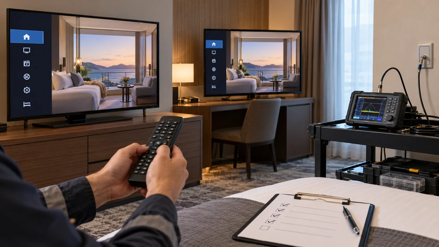
Build a controlled baseline with an authorized source, the proposed modulator configuration and a compatible test receiver. Then test representative rooms using the actual distribution path. Include the least flexible receiver family and outlets that represent different branches or signal conditions.
- Save the current state. Back up headend settings, source profiles and room-TV channel lists where the equipment supports it.
- Verify one proposed service. Confirm input acquisition, encoding, tuning, programme name, picture and sound.
- Apply the intended workload. Activate the planned sources and carriers together, then check capacity and distribution conditions.
- Test operational changes. Exercise source restart, modulator restart, TV power interruption and the agreed channel-list procedure.
- Expand in a controlled group. Change a defined set of rooms or one branch first and record its acceptance result.
Set the rollback trigger before the change window
Agree which failures require restoration: loss of an existing essential service, unacceptable receiver compatibility or a problem that cannot be resolved within the approved window. Identify who can authorize the decision and what configuration will be restored.
Where the network design permits parallel testing, isolate the test path so that it cannot collide with live carriers. Where a frequency must be reused, document the moment of change and its effect on existing channel lists. Do not assume a remote-control number can hide an RF conflict.
Use the professional HDMI modulator RF acceptance checklist for measured comparison and commissioning evidence. Add operational checks for channel order, sound recovery and staff instructions. A picture seen once in a sample room does not complete the acceptance process.
Prepare a room-access and staff communication plan as part of the change window. Identify whether televisions need rescanning, a supported channel-list import or no room-side action. Give staff the accepted lineup and a short escalation procedure. After the pilot group passes, retain a record of which rooms have changed so that a partial rollout can be completed or reversed without guessing. Confirm restoration on a representative receiver rather than assuming that loading a backup also restores its cached channel list.
Plan expansion and distinguish RF from interactive services
Reserve expansion at each relevant resource: input processing, encoding, transport capacity, RF spectrum, combining hardware, rack space and maintenance access. “Spare channels” should name which resource remains available and under which operating assumptions.
Before adding a service, update the source inventory and capacity budget. Confirm new metadata will not conflict with the existing lineup and repeat the receiver checks affected by the change. Keep an unchanged reference service during testing so that a distribution-wide problem is distinguishable from a fault in the new programme.
Choose a migration path from the required guest experience
Common RF channels can support a useful shared lineup over compatible coax infrastructure. Guest-specific menus, on-demand sessions, PMS workflows and individualized services involve additional applications and endpoints. An HDMI to RF modulator alone does not provide those functions.
If the project requires them, review an IPTV solution for hotels alongside the retained RF system. A phased design may use different delivery paths for different building areas. The design still needs separate capacity, receiving and operational records for each path.
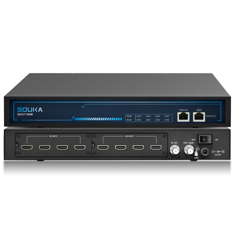
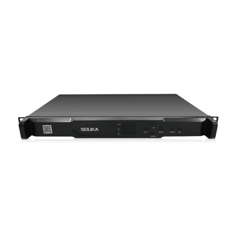
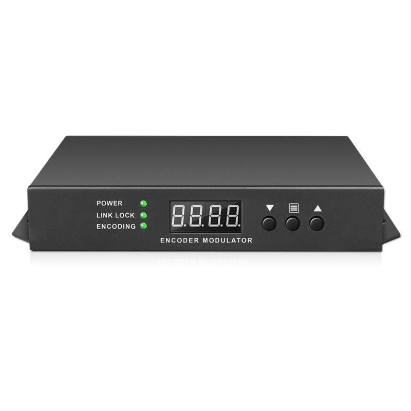
For procurement, send SOUKA the completed receiver matrix, source list, planned services and existing network information. Ask for confirmation of the exact supported operating combination and installation scope. Treat product pages as configuration starting points, not proof that every model has the same input count, RF mode or management features.
Related Products
Related Solutions
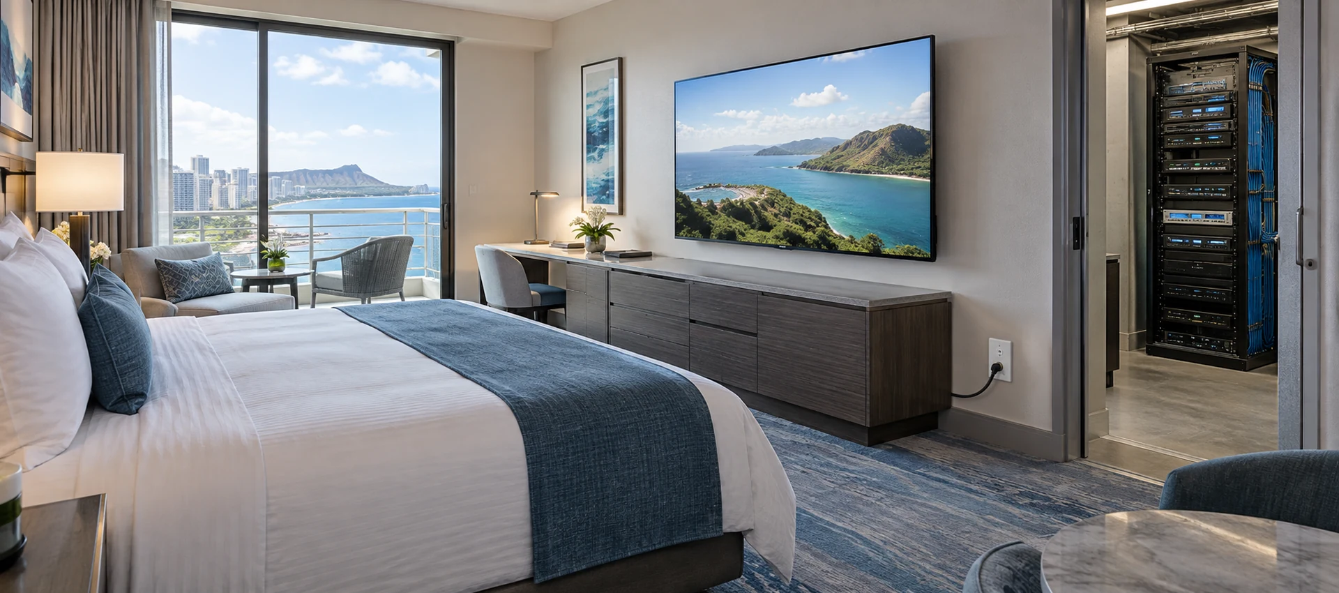
Cable TV Solution for Hotels
Deliver stable live television to every guest room without rebuilding the property network. SOUKA combines multi-source reception, high-density digital or analog modulation, RF combining, amplification, and centralized headend management for new hotels, phased renovations, and legacy coax upgrades.
Explore Solutions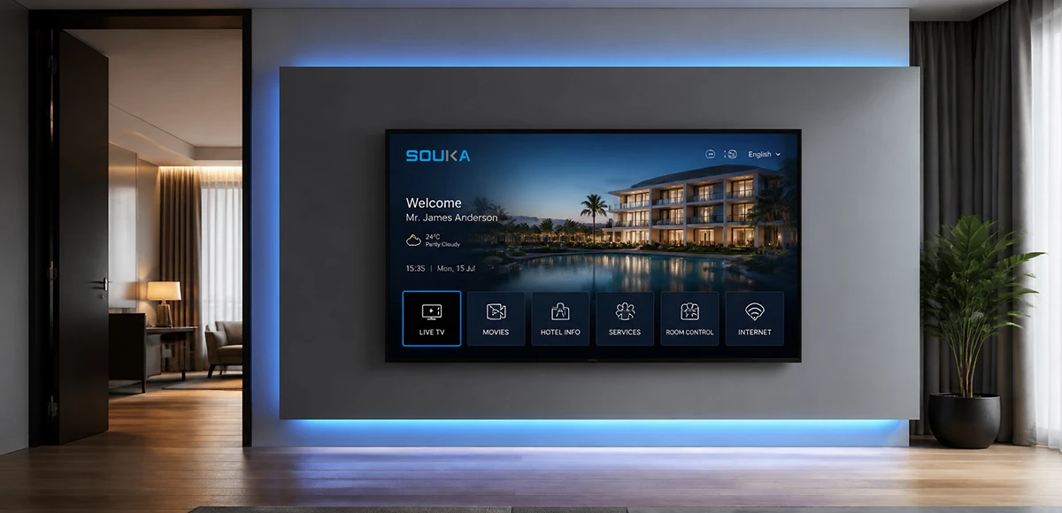
IPTV Solution for Hotels
Deliver lag-free 4K live TV to every guest room, customize your interactive brand interface with zero coding, and automate database workflows. Our carrier-grade Linux streaming matrix bridges natively with global property management systems to eliminate integration friction and slash hardware deployment overhead.
Explore Solutions
Cable TV Solution for Hotels
Deliver stable live television to every guest room without rebuilding the property network. SOUKA combines multi-source reception, high-density digital or analog modulation, RF combining, amplification, and centralized headend management for new hotels, phased renovations, and legacy coax upgrades.
Explore Solutions
IPTV Solution for Hotels
Deliver lag-free 4K live TV to every guest room, customize your interactive brand interface with zero coding, and automate database workflows. Our carrier-grade Linux streaming matrix bridges natively with global property management systems to eliminate integration friction and slash hardware deployment overhead.
Explore SolutionsFrequently Asked Questions
Conclusion: approve the channel plan before ordering
A reliable HDMI to RF modulator project begins with a traceable channel plan. Separate source count, encoded services, transport capacity, RF carriers and the numbers guests select. Confirm the receiving televisions, survey the existing spectrum and record service identities before approving equipment quantities.
Use a representative pilot to validate the whole operating combination. Preserve a working baseline, test the planned workload and define a reversible cutover. That approach gives procurement, installation and hotel operations one consistent reference for both launch and later expansion.
Contact SOUKA for a hotel TV channel-plan review with your source inventory, TV models, required lineup and coax network drawing. Request a model-specific configuration, confirmation of unresolved fields and a clear commissioning scope before placing the order.